Electric Circuit Analysis: Unit V: Resonance and coupled circuits
Dot rule for couple circuits
When the voltage induced by self and mutual inductance (L and M respectively) occur simultaneously, the relative polarities of these two voltages must be determined before making any circuit calculation.
DOT RULE FOR COUPLE CIRCUITS
When
the voltage induced by self and mutual inductance (L and M respectively) occur
simultaneously, the relative polarities of these two voltages must be
determined before making any circuit calculation. The voltage induced in a coil
by M may either aid or oppose the voltage of L, depending upon the sense of the
windings and the directions of the currents in the coils. It means that M di2
/ dt in coil 1 coil 1 may either be
positive or negative with respect to the drop L1 di1/dt in coil 1 .
This condition is taken into account by assigning to M either a positive or
negative sign.
To
simplify the representation of coupled circuits, coils are marked with dots. It
is to identify the polarities of mutual e.m.f.s. The dot is marked as explained
below:
(a)
Select a current direction in 1 coil.
(b)
Place a dot at terminal of the coil where the current enters the coil.
(c)
Apply the right hand rule to the coil and find the direction of flux.
(d)
Apply the Lenz's law to the second coil. The flux in the second coil will
oppose the original flux.
(e)
Apply the right hand rule to the second coil. The voltage of mutual inductance
is positive at the terminal where the current leaves the winding.
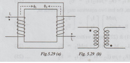
(f)
Hence place a dot at the terminal of the second coil where the natural current
leaves the winding, it is as shown in the fig. 5.29 (a).
Now,
the coupled coils shown on the core in fig. 5.29 (a) can be represented as
shown in fig.5.29(b). So, there is no need of showing the core.
Statement of Dot Rule
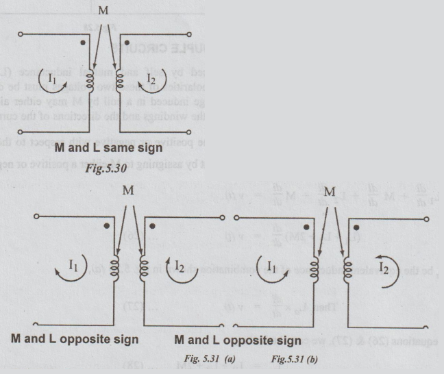
1.
If both currents enter dotted ends of coupled coils or if both currents enter
undotted ends, then the signs on the M-terms will be same as the signs on the
L-terms.
2.
If one current enters a dotted end and the other an undotted end, the signs on
the M-terms will be opposite to the signs on the L-terms.
The
above statements are explained with the figures. i.e., fig. 5.23 (a), (b), 5.24
(c), (d).
Electric Circuit Analysis: Unit V: Resonance and coupled circuits : Tag: : - Dot rule for couple circuits
Related Topics
Related Subjects

Electric Circuit Analysis
EE3251 2nd Semester 2021 Regulation | 2nd Semester EEE Dept 2021 Regulation