Electrical Machines: Unit IV: Single Phase Transformer
E.M.F. Equation of a Transformer
• When the primary winding is excited by an alternating voltage V1, it circulates alternating current, producing an alternating flux ϕ.
E.M.F.
Equation of a Transformer
AU May-04,05,07,12,14,15, Nov.-07,
Dec.-12,17
•
When the primary winding is excited by an alternating voltage V1, it
circulates alternating current, producing an alternating flux ϕ.
•
The primary winding has N1 number of turns. The alternating flux o
linking with the primary winding itself induces an e.m.f. in it denoted as E1.
•
The flux links with secondary winding through the common magnetic core. It
produces induced e.m.f. E2 in the secondary winding. This is
mutually induced e.m.f.
•
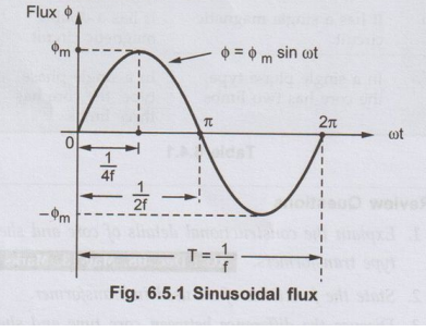
The primary winding is excited by purely sinusoidal alternating voltage. Hence
the flux produced is also sinusoidal in nature having maximum value of ϕm
as shown in the Fig. 6.5.1.
The
various quantities which affect the magnitude of the induced e.m.f. are:
Φ
= Flux and
ϕm
= Maximum value of flux
N1
= Number of primary winding turns
f
= Number of secondary winding turns
E1
= Frequency of the supply voltage
E2
= R.M.S. value of the primary induced e.m.f.
•
From Faraday's law of electromagnetic induction the average e.m.f. induced in
each turn is proportional to the average rate of change of flux.
Average
e.m.f. per turn
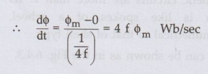
• Consider the ¼th cycle of the flux as shown in the Fig. 6.5.1. Complete cycle gets completed in 1/f seconds. In ¼ th time period, the change in flux is from 0 to ϕm
as
dt for ¼ th time period is ¼ f seconds
Average e.m.f. per turn = 4 f ϕm
•
As ϕ is sinusoidal, the induced e.m.f. in each turn of both the windings is
also sinusoidal in nature.
For
sinusoidal quantity,
Form
Factor = R.M.S. value / Average value = 1.11
R.M.S.
S. value = 1.11 × Average value
R.M.S.
value of induced e.m.f. per turn
=
1.11 x 4 f ϕm = 4.44 f ϕm
•
There are N1 number of primary turns hence the R.M.S. value of
induced e.m.f. of primary denoted as E1 is,
E1
= N1 x 4.44 f ϕm volts
•
While as there are N2 number of secondary turns the R.M.S. value of
induced e.m.f. of secondary denoted E2 is,
E2
= N2 × 4.44 f ϕm volts
•
The expressions of E1 and E2 are called e.m.f. equations
of a transformer.
E1
= 4.44 f ϕm N1 volts...(6.5.1)
E2
= 4.44 f ϕm N2 volts.....(6.5.2)
1. Concept of Ideal Transformer
•
A transformer is said to be ideal if it satisfies following properties :
i)
It has no losses.
ii)
Its windings have zero resistance.
iii)
Leakage flux is zero i.e. 100 % flux produced by primary links with the
secondary.
iv)
Permeability of core is so high that negligible current is required to
establish the flux in it.
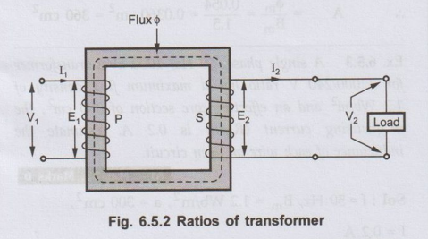
2. Ratios of a Transformer
•
Consider a transformer shown in Fig. 6.5.2 indicating various voltages and
currents.
1. Voltage ratio:
We know from the e.m.f. equations,
E1
= 4.44 f ϕm N1 and
E2
= 4.44 f ϕm N2
Taking
ratio of the two equations we get,
E2
/ E1c = N2 / N1
= K
This
ratio of secondary induced e.m.f. to primary induced e.m.f. is known as voltage
transformation ratio denoted as K.
Thus,
E2 = K E1 where K = N2/ N1.
1.
If N2 > N1 i.e. K > 1, we get E2 > E1
then the transformer is called step-up transformer.
2.
If N2 < N1 i.e. K < 1, we get E2 < E1,
then the transformer is called step-down transformer.
3.
If N2 = N1 i.e. K = 1, we get E2 = E1
then the transformer is called isolation transformer or 1:1 transformer.
2. Current ratio :
For an ideal transformer there are no losses. Hence the product of primary
voltage V1 and primary current I1, is same as the product
of secondary voltage V2 and the secondary current 12.
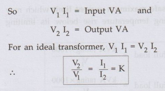
Hence
the currents are in the inverse ratio of the voltage transformation ratio.
3. Volt-Ampere Rating
•
When electrical power is transferred from primary winding to secondary there
are few power losses in between. These power losses appear in the form of heat
which increase the temperature of the device.
•
This temperature must be maintained below certain limiting value as it is
always harmful from insulation point of view.
•
The copper loss (I2R) in the transformer depends on the current 'I'
through the winding while the iron or core loss depends on the voltage 'V' as
frequency of operation is constant.
•
None of these losses depend on the power factor (cos ϕ) of the load. Hence
losses decide the temperature rise and hence the rating of the transformer.
•
As losses depend on V and I only, the rating of the transformer is specified as
a product of these two parameters V×L Hence the transformer rating is specified
as the product of voltage and current are called VA rating.
•
On both sides, primary and secondary VA rating remains same. This rating is
generally expressed in kVA (kilo volt amperes rating).
kVA
rating of a transformer =V1 I1 / 1000 = V2 I2
/ 1000 ........ 1000 to express in KVA
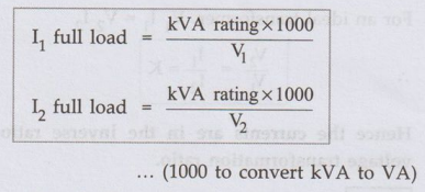
4. Full Load Currents
•
If V1 and V2 are the terminal voltages of primary and
secondary then from specified kVA rating we can decide full load currents of
primary and secondary, I1 and I2.
•This
is the safe maximum current limit which may carry, keeping temperature rise
below its limiting value.
•
These values indicate, how much maximum
load can be connected to a given transformer of a specified kVA rating.
The
full load primary and secondary currents indicate the safe maximum values of
currents which transformer windings can carry.
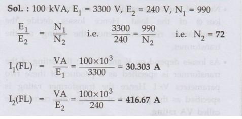
Ex. 6.5.1
A 100 kVA, 3300 V/240 V, 50 Hz, Single
phase transformer has 990 turns on the primary. Calculate the number of turns
on secondary and the approximate value of primary and secondary full load
currents. AU May-15, Marks 10
Sol. :
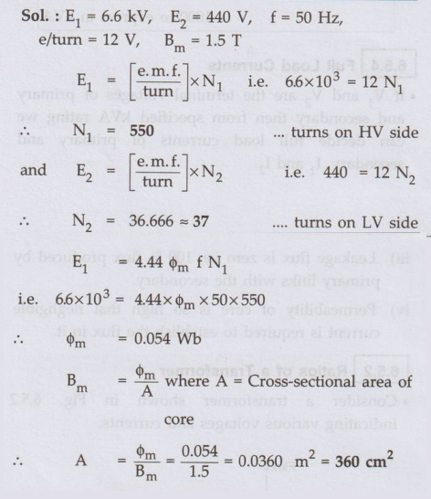
Ex. 6.5.2 The e.m.f. per turn of a
single-phase, 6.6 kV, 440 V, 50 Hz transformer is approximately 12 V. Calculate
number of turns is the HV and LV windings and the net cross-sectional area of
the core for a maximum flux density of 1.5 T.
Sol. :
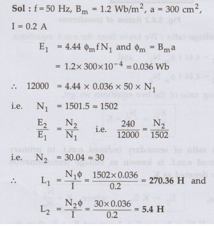
Ex. 6.5.3
A single phase, 50 Hz, 1000 kVA
transformer the for 12000/240 V ratio has a maximum flux density of 1.2 Wb/m2
and an effective core section of 300 cm2, magnetising current (RMS)
is 0.2 A. Estimate the inductance of each wire on open circuit. AU
May-12, Marks 6
Sol. :
Ex. 6.5.4 The
voltage per turn of a single phase transformer is 1.1 volt, when the primary
winding is connected to a 220 volt, 50 Hz AC supply the secondary voltage is
found to be 550 volt. Find the primary and secondary turns and core area if
maximum flux density is 1.1 Telsa. AU
Dec.-12, Marks 8
Sol. :
Refer
example 6.5.2 for the procedure and verify the answers as, N1 = 200,
N2 = 500,A= 45.04 cm2
Review Questions
1. Develop an equation
for induced e.m.f. in a transformer winding in terms of flux and frequency. AU May-04, 05, 12,
14, Dec.-12,17, Marks 8
2. State the
relationships between voltages and currents on primary side and secondary side
of a single phase transformer.
3. Explain the
various features of an ideal transformer.
4. What is kVA rating
of a transformer?
5. A single phase
transformer has 480 turns on primary and 90 turns on the secondary. The mean
length of flux path in the core is 1.8 m and joints are equivalent to an air
gap of 1 mm. The maximum value of the flux density is to be 1.1 T when a
potential difference of 2200 volts at 50 Hz is applied to the primary. Assume
value of magnetic field strength corresponding to the flux density of 1.1 T in
the core to be 400 A/m. Calculate
i) The cross-section
area of the core ii) Maximum value of the magnetizing current
iii) Secondary
voltage on no load.
[Ans. : i) 0.01876 m2
ii) 1.500 A iii) 412.5 volts]
6. A single-phase, 50 Hz transformer has 80
turns on the primary winding and 400 turns on the secondary winding. The net
cross-sectional area of the core is 200 cm2. If the primary winding
is connected to a 240 V, 50 Hz supply, determine: i) The e.m.f. induced in the
secondary winding. ii) The maximum value of the flux density in the core. [Ans.: E2 =
1200 V, Bm = 0.6756 Wb/m2]
7. A single phase
transformer has 350 primary and 1050 secondary turns. The primary is connected
to 400 V, 50 Hz a.c. supply. If the net cross sectional area of the core is 50
cm2, calculate i) The maximum value of the flux density in the core
ii) The induced e.m.f. in the secondary winding. [Ans. : Bm = 1.0296 Wb/m2, E2
= 1200 V]
8. A single phase
transformer has 500 turns on its primary and 1000 turns on secondary.
The voltage per turn
in the primary winding is 0.2 volts. Calculate,
i) Voltage induced in
the primary winding
ii) Voltage induced
in the secondary winding
iii) The maximum
value of the flux density if the cross section area of the core is 200 cm2
iv) kVA rating of the
transformer if the current in primary at full load is 10 A, the frequency is 50
Hz.
[Ans.: i) E1
= 100 volts, ii) E2 = 200 volts,iii)ϕm= 9.009 × 10⁻⁴
Wb iv) Bm= 0.045 web/m2 or Tesla ]
9. For a single phase
transformer having primary and secondary turns of 440 and 880 respectively,
determine the transformer kVA rating if half load secondary current is 7.5 A
and maximum value of on core flux is 2.25 mWb. [Ans.: 6.5934 KVA]
Electrical Machines: Unit IV: Single Phase Transformer : Tag: : - E.M.F. Equation of a Transformer
Related Topics
Related Subjects

Electrical Machines I
EE3303 EM 1 3rd Semester EEE Dept | 2021 Regulation | 3rd Semester EEE Dept 2021 Regulation