Electrical Machines II: UNIT I: a. Synchronous Generator
E.M.F. Equation of an Alternator
with Solved Example Problems | Synchronous Generator
This is the basic e.m.f. equation for an induced e.m.f. per phase for full pitch, concentrated type of winding.
E.M.F. Equation of an Alternator
AU
: Nov. 04, April-99, Dec.-07, 08, 09, 12, 13, 15, 16, May-04, 05, 06, 07,
09,10, 11, 12, De. 17
Let ϕ = Flux per pole, in Wb, P = Number of poles
Ns
= Synchronous speed in r.p.m., f = Frequency of induced e.m.f. in Hz
Z
= Total number of conductors
Zph
= Conductors per phase connected in series
Zph
= Z/3
Consider
a single conductor placed in a slot.
The
average value of e.m.f. induced in a conductor = dϕ / dt
For
one revolution of a conductor
eavg
per conductor = Flux cut in one revolution / Time taken one revolution
Total
flux cut in one revolution is ϕ × P
Time
taken for one revolution is 60/NS seconds.
eavg
per conductor = ϕP/(60/NS) = ϕ PNS/60 …(1.12.1)
But
f = PNS/120
Hence
PNS/60 = 2f
Substituting
in equation (1.12.1),
eavg
per conductor = 2f ϕ volts
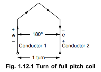
Assume
full pitch winding for simplicity i.e. this conductor is connected to a
conductor which is 180° electrical apart. So these two e.m.f.s will try to set
up a current in the same direction i.e. the two e.m.f. are helping each other
and hence resultant e.m.f. per turn will be twice the e.m.f. induced in a
conductor.
E.M.F.
per turn = 2 × (e.m.f. per conductor) = 2 × (2f ϕ) = 4f ϕ volts.
Let
Tph be the total number of turns per phase connected in series.
Assuming concentrated winding, we can say that all are placed in single slot
per pole per phase. So induced e.m.f.s in all turns will be in phase as placed
in single slot. Hence net e.m.f. per phase will be algebraic sum of the e.m.f.s
per turn.
Average
Eph = Tph × (Average e.m.f. per turn)
.-.
Average Eph = Tph × 4 f ϕ
But in a.c. circuits R.M.S. value of an alternating quantity is used for the analysis. The form factor is 1.11 of sinusoidal e.m.f.
Kf
= R.M.S./ Average = 1.11
R.M.S.
value of Eph = Kf × Average value
Eph
= 1.11 × 4 f ϕ Tph
Eph
= 4.44 f ϕ Tph volts
Key Point : This is
the basic e.m.f. equation for an induced e.m.f. per phase for full pitch,
concentrated type of winding.
Where
Tph = Number of turns per phase
Tph
= Zph/2 …. As 2 conductor constitute 1 turn
But
as mentioned earlier, the winding used for the alternators is distributed and
short pitch hence e.m.f. induced slightly gets affected. Let us see now the
effect of distributed and short pitch type of winding on the e.m.f. equation.
1. Pitch Factor or Coil Span Factor (Kc)
In
practice short pitch coils are preferred. So coil is form by connecting one
coil side to another which is less than one pole pitch away. So actual coil
span is less than 180°. The coil is generally shorted by one or two slots.
Key Point : The
angle bp which coils are short pitched is called angle of short pitch denoted
as ‘ɑ’.
ɑ
= Angle by which coils are short pitched. As coils are shorted in terms of
number of slots i.e. either by one slot, two slots and so on and slot angle is
3 then angle of short pitch is always a multiple of the slot angle β.
ɑ
= β × Number of slots by which coils are short pitched.
or
ɑ = 180° - Actual coil span of the coils.
This
is shown in the Fig. 1.12.2.

Now
let E be the induced e.m.f. in each coil side. If coil is full pitch coil, the
induced e.m.f. in each coil side help each other. Coil connections are such
that both will try to set up a current in the same direction in the external
circuit Hence the resultant e.m.f. across a coil will be algebraic sum of the
two.
ER
= E + E = 2E ... For full pitch
Now
the coil is short pitched by angle 'a', the two e.m.f. in two coil sides no
longer remains in phase from external circuit point of view. Hence the
resultant e.m.f. is also no longer remains algebraic sum of the two but becomes
a phasor sum of the two as shown in the Fig. 1.12.4.
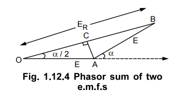
Obviously
ER in such a case will be less than what it is in case of full pitch coil.
From
the geometry of the Fig. 1.12.4, we can write,
AC
is perpendicular drawn on OB bisecting OB.
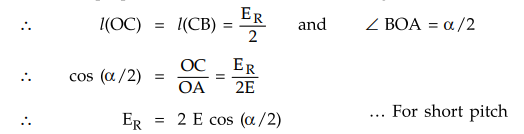
This
is the resultant e.m.f. in case of a short pitch coil which depends on the
angle of short pitch 'ɑ'.
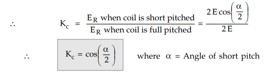
Key Point : The factor by
which, induced e.m.f gets reduced due to short pitching is called pitch factor
or coil span factor denoted by Kc.
It
is defined as the ratio of resultant e.m.f. when coil is short pitch to the
resultant e.m.f. when coil is full pitched. It is always less than one. It is
also defined as the ratio of phasor sum of e.m.f.s to algebraic sum of e.m.f.s.
2. Distribution Factor (Kd)
Similar
to full pitch coils, concentrated winding is also rare in practice. Attempt is
made to use all the slots available under a pole for the winding which makes
the nature of the induced e.m.f. more sinusoidal. Such a winding is called
distributed winding.
Consider
18 slots, 2 pole alternator. So slots per pole i.e. n = 9.
m
= Slots per pole per phase = 3 and β = 180°/ 9 = 20°
Let
E = Induced e.m.f. per coil and there are 3 coils per phase.
In
concentrated type all the coil sides will be placed in one slot under a pole.
So induced e.m.f. in all the coils will achieve maxima and minima at the same
time i.e. all of them will be in phase. Hence resultant e.m.f. after connecting
coils in series will be algebraic sum of all the e.m.f.s as all are in phase.
As
against this, in distributed type, coil sides will be distributed, one each in
the 3 slots per phase available under a pole as shown in the Fig. 1.12.5 (a).
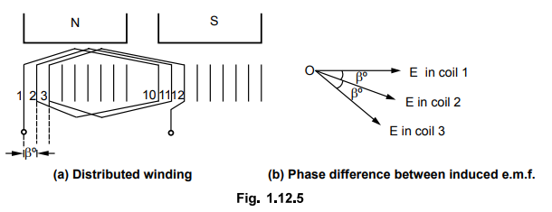
Fig.
1.12.5
Though
the magnitude of e.m.f. in each coil will be same as 'E', as each slot
contributes phase difference of 3° i-e. 20° in this case, there will exist a
phase difference of 3° with respect to each other as shown in the Fig. 1.12.6
(b).
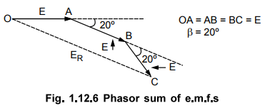
Hence
resultant e.m.f. will be phasor sum of all of them as shown in the Fig. 1.12.6.
So due to distributed winding resultant e.m.f. decreases.
Key Point : The factor by
which there is a reduction in the e.m.f. due to distribution of coils is called
distribution factor denoted as Kd.
a.
Derivation of Distribution Factor
In
general let there be 'n' slots per pole and zm' slots per pole per phase. So
there will be 'm' coils distributed under a pole per phase, connected in
series. Let E be the induced e.m.f. per coil. Then all the'm' e.m.f.s induced in
the coils will have successive phase angle difference of β = 180o/n.
While finding out the phasor sum of all of them, phasor diagram will approach a shape of a 'm'
equal sided polygon circumscribed by a semicircle of radius 'R'.
This
is shown in the Fig. 1.12.7 (a) AB, BC, CD etc., represent e.m.f. per coil. All
the ends are joined at 'O' which is centre of the circumscribing semicircle of
radius 'R'.
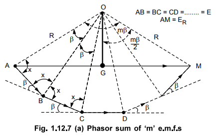
Fig.
1.12.7 (a) Phasor sum of ‘m’ e.m.f.s
Angle
subtended by each phasor at the origin 'O' is 3°. This can be proved as below.
All
the triangles OAB, OBC ... are similar and isosceles, as AB = BC = CD = ... =
E.
Let
the base angles be 'x'.
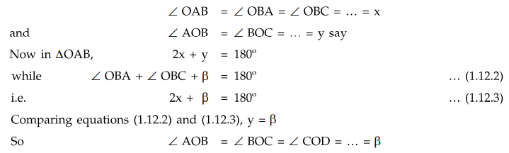
If
'M' is the last point of the last phasor,
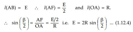
∠ AOM = m × β = mβ and
AM
= ER = Resultant of all the e.m.f.s.
Consider a ∆OAB separately as shown in the Fig. 1.12.7 (b).
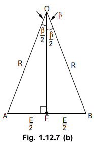
Let
OF be the perpendicular drawn on AB bisecting angle at apex 'O' as β /2.
Now
consider ∆OAM as shown in the Fig. 1.12.7 (a) and OG is the perpendicular drawn
from 'O' on its base bisecting ∠OAM.
This
is the resultant e.m.f. when coils are distributed. If all zm' coils are
concentrated, all would have been in phase giving ER as algebraic
sum of all the e.m.f.s.
ER
= m × E ... For concentrated
From equation (1.12.4), E = 2R sin (β/2)
ER
= 2 m R sin (β/2)
This is resultant e.m.f. when coils are concentrated.
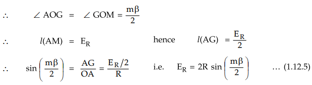
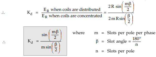
The
distribution factor is define as the resultant e.m.f. when coils are disturbed
to the resultant e.m.f. when coils are concentrated. It is always less than
one.
This
factor is also called winding factor or breadth factor.
3. Generalized Expression for E.M.F. Equation of an Alternator
Considering
full pitch, concentrated winding,
Eph
= 4.44 f ϕ Tph volts.
But
due to short pitch, distributed winding used in practice, this Eph will reduce
by factors Kc and Kd. So generalized expression for
e.m.f. equation can be written as
Eph
= 4.44 Kc Kd f ϕ Tph volts.
For
full pitch coil, Kc, = 1.
For
concentrated winding Kd = 1.
Key Point : For short pitch and
distributed winding Kc and Kd are always less than unity.
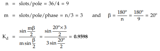
Example
: 1.12.1 Calculate the distribution factor for a
36 slots, 4 poles, single layer three phase winding.
Solution
:
Example
: 1.12.2 Calculate the pitch factor for the given
winding : 36 stator slots, 4 poles, coil
Solution
:
36
slots, P = 4, Coil span 1-8.
n
= Slots / Pole = 36 / 4
For
full pitch, coil span must be 1-9 but actually it is 1- 8. Thus coils are short
pitched by 1 slot. Hence short pitch angle is one slot angle.
β
= slot angle = 180° / n = 20°
ɑ
= Angle of short pitch = 1 slot angle = 20°
Kc
= Pitch factor = cos ɑ /2 = cos 10° = 0.9848
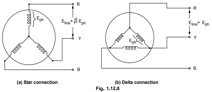
4. Line Value of Induced E.M.F.
If
the armature winding of three phase alternator is star connected, then the
value of induced e.m.f. across the terminals is √3 Eph where Eph
is induced e.m.f. per phase.
While
if it is delta connected line value of e.m.f. is same as Eph.
This
is shown in the Fig. 1.12.8 (a) and (b).
Advantages
of star connection :
Practically
most of the alternators are star connected due to following reasons :
1.
Neutral point can be earthed from safety point of view.
2.
For the same phase voltage, voltage available across the terminal is more than
delta connection.
3.
For the same terminal voltage, the phase voltage in star is 1/√3
times line value.
This
reduces strain on the insulation of the armature winding.
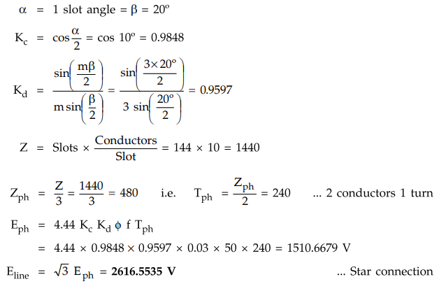
Example
1.12.3 A 3 phase, 50 Hz, 16 pole star connected
alternator has a stator winding with 144 slots with 10 conductors/slot. The
magnetic flux/pole is 0.03 webers and is sinusoidally distributed in space. The
coil pitch of the winding is 8 slots. Estimate the e.m.f induced between the
lines of the alternator.
Solution
: P = 16, f = 50
Hz, 144 slots, 10 conductors/slot
ϕ
= 0.03 Wb, Coil pitch = 8 slots.
n
= Slots / pole = 144/16 = 9 and m = Slots
/ pole / phase
=
n/3 = 9/3 = 3
β
= 180° / n = 180°/9 = 20o
For
full pitch, coil pitch = n = 9 slots but actual coil pitch is 8 slots. So coils
are short pitched by 1 slot.
ɑ
= 1 slot angle = β = 20°
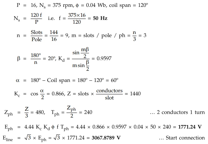
Example
1.12.4 A 3-phase 16 pole alternator has star connected
winding with 144 slots and10 conductors per slot. The flux per pole is 0.04 Wb
and is distributed sinusoidally. The speed is 375 rpm. Find the frequency, phase
emf and line emf. The coil span is 120° electrical AU : Dec.-13, Marks 8
Solution
:
Example
1.12.5 A three phase, star-connected 16 pole alternator
has 192 slots with 8 conductors/slot, coil spain = 160 electrical degrees, speed
of alternator = 375 r.p.m., flux/pole = 55 mWb. Calculate the phase and line
voltages. AU : Nov.-04, Marks 8
Solution
:
Refer Ex. 1.12.4 for the procedure and verify the answer as Eline
= 5 kv.
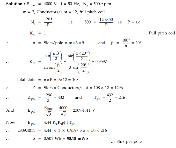
Example
1.12.6 A 3 ph, Y connected alternator has the following
data : Voltage required to be generated on O.C. is 4000 V at 50 Hz, speed is
500 r.p.m., stator slots/pole/ph is 3, conductors/slot is 12. Calculate the
number of poles and useful flux/pole. Assume all conductors/ph to be connected
in series and coil to be full pitched. AU : May-05, Marks 8
Solution
:
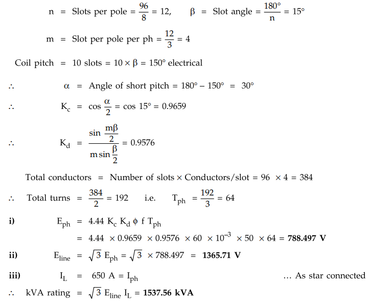
Example
1.12.7 A 3 phase, 8 pole, 50 Hz, star connected alternator
has 96 slots with 4 conductors per slot. The coil pitch is 10 slots. If the
flux per pole is 60 mWb find
i)
The phase voltage
ii)
The line voltage
iii)
If each phase is capable of carrying 650 A, what is the kVA rating of the
machine ?
Solution
: Given
values are,
P
= 8, f = 50 Hz, ϕ = 60 mWb,
Coil
pitch = 10 slots, No. of slots = 96
Example
1.12.8 A 3 phase, 6 pole, star-connected alternator
revolves at 1000 r.p.m. The stator has 90 slots and 8 conductors per slot. The
flux per pole is 0.05 Wb (sinusoidally distributed). Calculate the voltage
generated by the machine if the winding factor is 0.96. AU : May-06,
Marks 6
Solution
: Refer Ex. 1.12.4
for the procedure and verify the answer as
Eline
= 2214.808 V
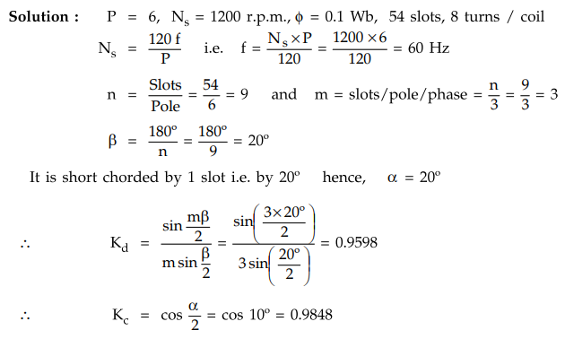
Example
1.12.9 Find the no load phase and line voltage of a star
connected 3 phase, 6 pole alternator which runs at 1200 r.p.m., having flux per
pole of 0.1 Wb sinusoidally distributed. It’s stator has 54 solts having double
layer winding. Ecah coil has 8 turns and the coil chorded by 1 slot.
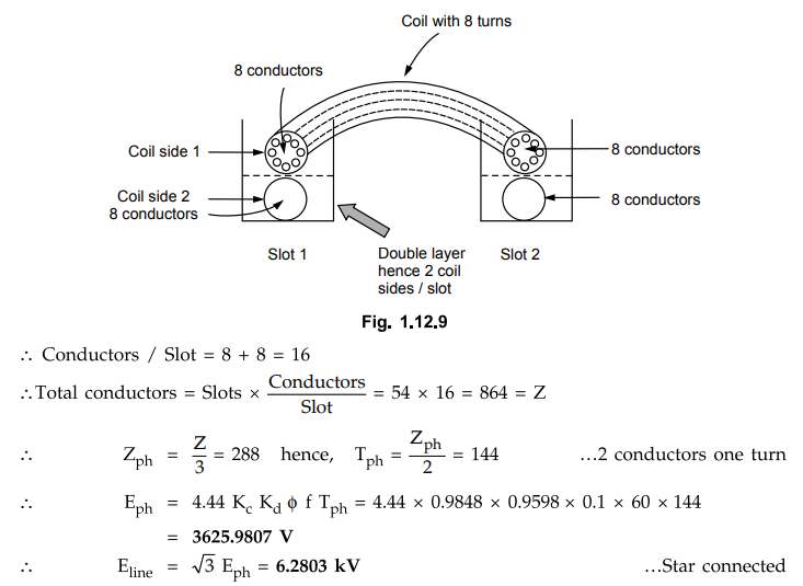
Now
winding is double layer means in each slot there are two coil sides and each
coil has 8 turns. Thus each coil side has 8 conductors as shown in the Fig.
1.12.9.
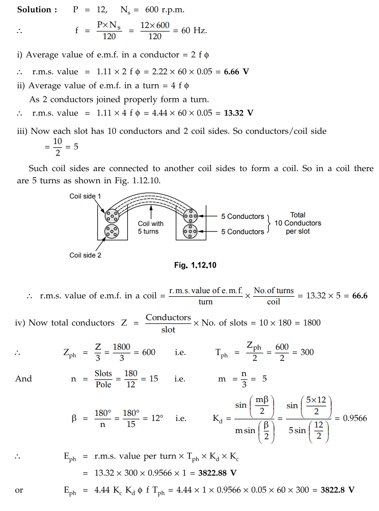
Example
1.12.10 A 12 pole, three phase, 600 r.p.m., star connected
alternator has 180 slots. There are 2 coil sides per slot and total 10
conductors per slot. If flux per pole is 0.05 Wb determine from first
principles,
i)
R.M.S. value of e.m.f. in a conductor
ii)
R.M.S. value of e.m.f. in a turn
iii)
R.M.S. value of e.m.f. in a coil iv) Per phase induced e.m.f.
Assume
full pitch coils.
Solution
:
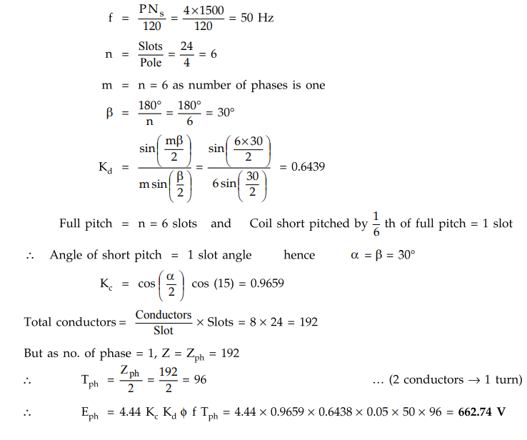
Example
1,12,11 A single phase 1500 r.p.m., 4 pole
alternator has 8 conductors per slot with total of 24 slots. The winding is
short pitched by th of full pitch. Assume distributed winding with flux per
pole as 0.05 Wb. Calculate the induced e.m.f.
Solution
:
NS = 1500 r.p.m., P = 4, Slots = 24; Conductors/slot = 8
Note
that the alternator is single phase and not the three phase.
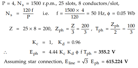
Example
1.12.12 A 4-pole alternator has an armatuure with 25
slots and 8 conductors per slot and rotates at 1500 r.p.m. and the flux per
pole is 0.05 Wb. Calculate the e.m.f. generated, if winding factor is 0.96 and
all the conductors are in series. AU : Dec.-12, Marks 4
Solution
:
P = 4, N5 = 1500 r.p.m., 25 slots, 8 conductors/slot,
Examples for practice
Example
1.12.13 A 3 phase, 16 pole alternator has a star
connected winding with 144 slots and 10 conductors per slot. The flux per pole
is 0.03 Wb, sinusoidally distributed and the speed is 375 r.p.m. Find the
frequency and line voltage.
[Ans.:
f = 50 Hz, Eline = 2656.94 V]
Example
1.12.14 In a 3 phase, star connected alternator, there
are 2 coil sides per slot and 16 turns per coil. Armature has 288 slots on its
periphery. When driven at 250 r.p.m. it produces 6600 V between the lines at 50
Hz. The pitch of the coil is 2 slots less than the full pitch. Calculate the
flux per pole.
[Ans.:
0 = 12 mWb]
Example
1.12.15 Calculate the distribution factor of a 3-phase
winding with 120° phase spread when the winding is i) Uniformly distributed ii)
Occupies 6 slots per pole.
[Ans.:
i) 0.8269, ii) 0.8365]
Example
1.12.16 Find the value of Kd for an alternator with 9
slots per pole for the following cases i) One winding in all the slots ii) One
winding using only the first 2/3 of the slots / pole iii) Three equal windings
placed sequentially in 60° group.
[Ans.:
i) 0.6398, ii) 0.8312, iii) 0.9597]
Example
1.12.17 The armature of a single phase alternator is
wound completely with T single turn coils, which are uniformly distributed. The
induced e.m.f. in each turn is 2 V (r.m.s.). Calculate the e.m.f. of the whole
winding with T number of coils connected in series.
[Ans
. E ph = 4 T/π V]
Example
1.12.18 A 3-phase, 16 pole, star connected alternator
has 144 slots having 10 conductors in each slot. The flux per pole is 30 mWb
and distributed sinusoidally and the speed is 375 r.p.m. Find the induced
e.m.f. for ; i) Full pitch winding ; ii) Coils short pitched by 1 slot ; iii)
Coils short chorded by 2 slots.
[Ans.:
1533.98 V, 2656.94 V, 1510.68 V, 2616.574 V, 1441.3318 V, 2496.46 V]
Example
1.12.19 A 3 - 0, 50 Hz, 10 pole alternator has 90 slots.
The flux per pole is 0.15 Wb. If the winding is to be star-connected to give a
line voltage of 11000 V, find the number of armature conductors to be connected
in series/phase.
[Ans.:
396]
Example
1.12.20 A 3 phase, 4 pole, 50 Hz star connected
alternator has flux per pole of 0.12 Wb. The slots per pole per phase is 4 and
the number of conductors per slot are 4. If the winding coil span is 150°,
calculate the emf generated
[Ans.:
788.5472 V, 1365.8038 V]
Review Questions
1. Derive the e.m.f.
equation of an alternator. Explain the pitch factor and distribution factor.
AU : May-04, 06, 07,
10, 11, Dec.-04, 06, 10, 11, 12, 13, 14, 15, 16, Dec.-17 Marks 12
2. Derive the
expression for the distribution factor and coil span factor.
Electrical Machines II: UNIT I: a. Synchronous Generator : Tag: Engineering Electrical Machines - II : with Solved Example Problems | Synchronous Generator - E.M.F. Equation of an Alternator
Related Topics
Related Subjects

Electrical Machines II
EE3405 Machine 2 EM 2 4th Semester EEE Dept | 2021 Regulation | 4th Semester EEE Dept 2021 Regulation