Electrical Machines II: UNIT III: a. Three Phase Induction Motor
Effect of Harmonics on Performance of 3 Phase induction Motor
The harmonics caused due to variation of air gap reluctance are called tooth or slot harmonics.
Effect of Harmonics on Performance of 3 Phase Induction Motor
The
induction motor performance is affected by the harmonics in the time variation
of the impressed voltage. But its effect on the performance of the motor is not
predominent hence it is not considered here.
The
torque-slip characteristics as discussed earlier is obtained when the space distribution
of flux wave along the air gap periphery is sinusoidal. But the air gap flux is
not purely sinusoidal as it contains odd harmonics (5th , 7th , 11th etc).
Hence at low speeds, the torque-slip characteristic is not smooth. The
distribution of the stator winding and the variation of air gap reluctance due
to stator and rotor slots are main causes of air gap flux harmonics.
The
harmonics caused due to variation of air gap reluctance are called tooth
or slot harmonics. Due to these harmonics produced in air gap flux,
unwanted torques are developed along with vibration and noise.
Now
eventhough stator currents are sinusoidal, the stator is not sinusoidal as stator winding has the number of slots not
more than 3 to 4 per phase. If we carry out analysis of stator m.m.f. with the
help of Fourier series it can be seen that in addition to fundamental wave it
contains odd harmonics m.m.f. waves.
The
third harmonic flux waves produced by each of the three phases neutralize each
other as it differs in time phase by 120°. Thus air gap flux does not contain
third harmonics and its multiples. The fundamental m.m.f. wave produces flux
which rotates at synchronous speed which is given as ns = 2f1 /
P r.p.s. where f1 is supply frequency and p is number of poles.
Similarly fifth harmonic m.m.f. wave produces flux which rotates at 2f1 /
5P = ns/5 r.p.s. and in a direction opposite to the fundamental
m.m.f. wave.
The
seven harmonic m.m.f. produces flux which rotates at ns/7 r.p.s. and
in the direction of fundamental m.m.f. wave.
Thus
it can be seen that harmonic m.m.f. wave produces flux which rotates at 1/ k times the fundamental speed and in the
direction of fundamental wave if k = 6m + 1 and in the reversed direction if k
= 6m - 1 where m is any integer. The most important and predominent harmonics
whose effects must be studied are 5 th and 7th harmonics.
The
electromagnetic torque that is developed in the induction motor is because of
zero relative speed between stator and rotor fields. This fact can be explained
as follows :
When
rotor is revolving in the same direction of rotation as the stator field, the
frequency of rotor currents is sf1 and the rotor field produced will have speed
of s rig r.p.m. with respect to rotor in the forward direction. But there is
mechanical rotation of rotor at n r.p.m. which is superimposed on this. The speed
of rotor field in space is thus given by sum of these speeds
sns
+ n = sns + ng (1 - s) = ns
The
stator and rotor fields are thus stationary with respect to each other which
produces a steady torque maintaining the rotation. This torque existing at any
mechanical speed n other than synchronous speed is called asynchronous torque.
The
fifth harmonic field rotates at ns/5 r.p.s. and in a direction
opposite to direction of rotor. Therefore slip of rotor with respect to fifth
harmonic field speed is
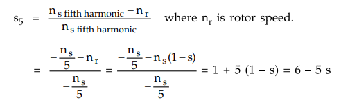
Here
- ns / 5 represents fifth harmonic field rotating opposite to the
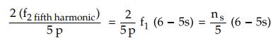
rotor. The frequency of rotor currents induced by fifth harmonic rotating field
is
f2
fifth harmonic = s5 × Stator frequency = (6 - 5s) × f1
Now
speed of fifth harmonic rotor field with respect to rotor is given by
Now,
speed of fifth harmonic rotor field with respect to stator
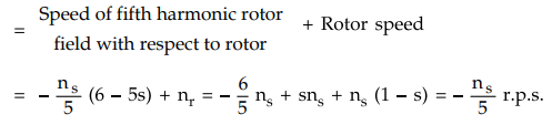
Negative
sign is used before ns / 5 (6 - 5s) which indicates 5th harmonic
field rotates opposite to rotor movement. Thus it can be seen that speed of
fifth harmonic stator field and rotor field is equal and relative speed between
the two is zero. Thus it produces 5th harmonic induction motor torque similar
to torque produced by fundamental component.
Similar
analysis can be made on 7th harmonic to show 7th harmonic torque produced
similar to fundamental one. Thus each space harmonic can be considered to
produce its own asynchronous torque. The induction motor can be considered as
equivalent to number of induction motors in series having poles equal to number
of harmonics multiplied by number of poles. The torque produced by fundamental
component and the harmonic are shown in the Fig. 5.20.1.
1. Crawling
As
fifth harmonic field rotates opposite to the rotor rotation, the torque
produced by fifth harmonic opposes fundamental torque and it acts as braking
torque on motor. The seventh harmonic field rotates in the direction of rotor
rotation, the torque produced by seventh harmonic aids the fundamental torque.
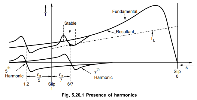
The resultant torque is shown in Fig. 5.20.1 which shows the addition of
fundamental, fifth harmonic and seventh harmonic torque. The fifth harmonic
torque is zero at ns / 5
r.p.s. while seventh harmonic torque is zero at + ns / 7.
There
are two dips which can be seen in the resultant torque, one is near the slip
1.2 and other near slip 6/7. The dip near s = 6 is more important as torque
here decreases with increase in speed. The load torque is shown in figure. The
motor will run at ns / 7 with X as the operating point. Thus stable
operation is obtained near sub-synchronous speed ns / 7 . This is
called crawling or asynchronous crawling. Due to crawling there is much higher
stator current accompanied by noise and vibration. The torque obtained from
induction motor here is called asynchronous torque.
When
two harmonic fluxes of same order one because of stator and the other because
of rotor interact with each other at one particular speed and produces harmonic
synchronous torque just like that produced in synchronous motor. These torque
are caused by tooth harmonics. The stable operation at subsynchronous speed
caused by slot harmonics is called synchronous crawling which is
associated with vibration and noise.
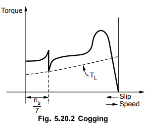
2. Cogging
A
special behaviour is shown by squirrel cage induction motor during starting for
certain combinations of number of stator and rotor slots. If number of stator
slots S1 are equal to number of rotor slots S2 or integral
multiple of rotor slots S2 then variation of reluctance as a
function of space will have pronounced effect producing strong forces than the
accelerating torque. Due to this motor fails to start. This phenomenon is
called cogging. Such combination
of stator and rotor slots should be avoided while designing the motor.
Let
the slots of stator and rotor be 24. The stator-slotting produces its tooth harmonics
of order 2S1 / P ± 1 whereas the rotor-slotting produces its tooth
harmonics of order 2S1 / P ± 1 where S1 and S2
are number of stator and rotor slots. The plus sign refers to the harmonic
field rotation in the direction of rotor.
Here
S1 = S2 so stator and rotor slot harmonics are same and
given by,
Let P = 4
2
× 24 / 4 ± 1 = 11 or 13
The
harmonics of order 11 produce backward rotating field for both stator and
rotor. The harmonics of order 13 produce forward rotating field.
The
two harmonic fields of same order say 11 harmonic would be stationary with
respect to each other only when
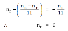
As
the harmonic field due to 11th harmonic rotates backward with respect to stator
hence negative sign is used for ns /ll.
Similarly,
for 13 harmonic produced by stator and rotor would be stationary with respect
to each other when
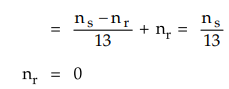
Hence
it can be seen that harmonic synchronous torque is produced at zero rotor
speed. The 11th and 13th harmonic fields produced by stator and rotor and
stationary with respect to each other. The harmonic synchronous torque is
produced at zero rotor speed and the motor will remain at rest. This is called
cogging. The torque speed characteristics with harmonic synchronous torque as
ns/7 is shown in the Fig. 5.20.2
The
stator slot harmonics of order 2S1
/ P± 1 may interact with rotor slot harmonics of order 2S1 / P± 1 to develope the harmonic synchronous
torques.
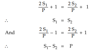
It
can be thus seen that if S1 = S2 or S1 – S2
= P then cogging will be definately observed in the induction motor.
The
cogging and crawling is not predominent in slip ring induction motor as these
motors are started with higher starting torques with external resistance in
rotor circuit.
The
crawling effect can be reduced by taking proper care during the design. Still
if crawling is observed then it can be overcome by applying a sudden external
torque to the driven load in the direction of rotor. If there is reduction in
supply voltage then torque also decreases (T ∝V21). Hence
asynchronous crawling may be observed which is absent under rated voltage
conditions. Thus asynchronous torques can not be avoided but can be reduced by
proper choice of coil span and by skewing the stator or rotor slots.
The
synchronous harmonics torques can be totally eliminated by proper combination
of stator and rotor slots.
Review Question
1. Explain briefly about crawling and cogging.
Applications
i)
Squirrel cage type of motors having moderate starting torque and constant speed
characteristics preferred for driving fans, blowers, water pumps, grinders,
lathe machines, printing machines, drilling machine.
ii)
Slip ring induction motors can have high starting torque as high as maximum
torque. Hence they are preferred for lifts, hoists, elevators, cranes,
compressors.
Review Question
1. State the applications of squirrel cage and wound rotor
induction motors.
Electrical Machines II: UNIT III: a. Three Phase Induction Motor : Tag: Engineering Electrical Machines - II : - Effect of Harmonics on Performance of 3 Phase induction Motor
Related Topics
Related Subjects

Electrical Machines II
EE3405 Machine 2 EM 2 4th Semester EEE Dept | 2021 Regulation | 4th Semester EEE Dept 2021 Regulation