Electrical Machines: Unit IV: Single Phase Transformer
Effect of Winding Resistances
Single Phase Transformer
• A practical transformer windings possess some resistances which not only cause the power losses but also the voltage drops. Let us see what is the effect of winding resistances on the performance of the transformer.
Effect of
Winding Resistances
AU: May-14
•
A practical transformer windings possess some resistances which not only cause
the power losses but also the voltage drops. Let us see what is the effect of
winding resistances on the performance of the transformer.
Let
R1 = Primary winding resistance in ohms
R2
= Secondary winding resistance in ohms
•
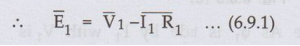
Now when current I1 flows through primary, there is voltage drop V1
R1 across the winding. The supply voltage V1 has to
supply this drop. Hence primary induced e.m.f. E1 is the vector
difference between V1 and I1 R1.
'•
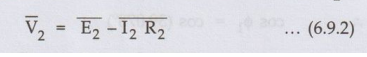
Similarly the induced e.m.f. in secondary is E2. When load is
connected, current I2
flows and there is voltage drop I2 R2. The e.m.f. E has
to supply this drop. The vector difference between E2 and I2
R2 is available to the load as a terminal voltage V2.
•
The drops I1 R1 and I2 R2 are
purely resistive drops hence are always in phase with the respective currents I1
and I2.
1. Equivalent
Resistance
•
The resistance of the two windings can be transferred to any one side either
primary or secondary without affecting the performance of the transformer. The
transfer of the resistances on any one side is advantageous as it makes the
calcuations very easy. Let us see how to transfer the resistances on any one
side.
The
total copper loss due to both the resistances can be obtained as,
Total
copper loss

.
Now the expression (6.9.3) indicates that the total copper loss can be
expressed as I12 R1 +I12 R2
/ K2 .This means R2 / K2 is the
resistance value of R2 shifted to primary side which causes same
copper loss with I1 as R2 causes with 12. This value of
resistance R2/K2 which is the value of R2 referred to
primary is called equivalent resistance of secondary referred to primary. It is
denoted as R '2.
R
'2
= R2 / K2...........(6.9.4)
•
Hence the total resistance referred to primary is the addition of R1
and R '2
called equivalent resistance of transformer referred to primary and denoted as R1e
R1e
= R1 + R '2 = R1 + R2 /
K2 (6.9.5)
•
This resistance R1e causes same copper loss with I1 as
the total copper loss due to the individual windings.
Total
copper loss = I12 R1e = I12
R1 +I12 R2...(6.9.6)
•
So equivalent resistance R1e simplifies the calculations as we have
to calculate parameters on one side only.
•
Similarly it is possible to refer the equivalent resistance to secondary
winding.
Total
copper lossv =

•
Thus the resistance K2 R1 is primary resistance referred
to secondary denoted as R'1.
R'1
= K2 R1 .....(6.9.8)
•
Hence the total resistance referred to secondary is the addition of R2
and R'1 called equivalent resistance of transformer referred to
secondary and denoted as R2e
R2e
= R2+ R'1 = R2+
K2 ....................
(6.9.9)
..
Total copper loss = I22 R2e ......(6.9.10)
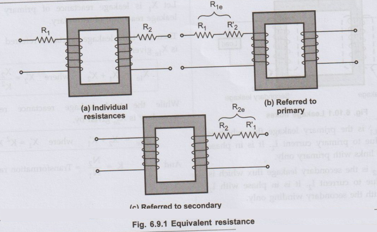
• The concept of equivalent resistance is shown in the Fig. 6.9.1 (a), (b) and (c).
Key Point:
When resistances are transferred to primary, the secondary winding becomes
resistance winding for calculation purpose. The entire copper loss occurs due
to R1e. Similarly when resistances are referred to secondary, the
primary becomes resistanceless for calculation purpose. The entire copper loss
occurs due to R2e.
Important Note:
•
When a resistance is to be transferred from the primary to secondary, it must
be multiplied by K2. When a resistance is to be transferred from the
secondary to primary, it must be divided by K2. Remember that K is N2/N1.
•
Thus the resistance K2 R1 is primary resistance referred
to secondary denoted as R '1.
R
'1
= K2 R1 ............. (6.9.8)
•
Hence the total resistance referred to secondary is the addition of R2
and R'1 called equivalent resistance of transformer referred to
secondary and denoted as R2e
R2e
= R2+ R'1 = R2+ K2 R1
.............(6.9.9)
Total copper loss = I22
R2e ...............(6.9.10)
•
The concept of equivalent resistance is shown in the Fig. 6.9.1 (a), (b) and
(c).
Key Point: When
resistances are transferred to primary, the secondary winding becomes
resistance winding for calculation purpose. The entire copper loss occurs due
to R1e. Similarly when resistances are referred to secondary, the
primary becomes resistanceless for calculation purpose. The entire copper loss
occurs due to R2e.
Important Note:
•
When a resistance is to be transferred from the primary to secondary, it must
be multiplied by K2. When a resistance is to be transferred from the
secondary to primary, it must be divided by K2. Remember that K is N2/N1.
The
result can be cross-checked by another approach. The high voltage winding is
always low current winding and hence the resistance of high voltage side is
high. The low voltage side is high current side and hence resistance of low
voltage side is low. So while transferring resistance from low voltage side to
high voltage side, its value must increase while transferring resistance from high
voltage side to low voltage side, its value must decrease.
Key
Point: High voltage side → Low current side →High
resistance side
Low
voltage side→ High current side → Low resistance side
Ex.
6.9.1 A 1-phase transformer has 360 turns and 180
turns respectively in its secondary and primary windings. The respective
resistance are 0.233 and 0.067. Calculate the equivalent resistance of
1)
The primary in terms of the secondary winding.hong
2)
The secondary in terms of the primary winding, and
3)
The total resistance of the transformer in terms of the primary. AU May-14, Marks 8
Sol.: N2 = 360, N1 = 180, R2 = 0.233 Ω, R1 = 0.067 Ω.
K
= N2 / N1 = 360 / 180
= 2
As secondary turns are more, secondary winding is high voltage side. Hence on secondary the resistance values are high.

Review Question
1. A 6600/400 V single phase transformer has primary resistance of 2.5 Ω and secondary resistance of 0.01 Ω. Calculate total equivalent resistance referred to primary and secondary.
[Ans.: 5.2225Ω, 0.01918 Ω]
Electrical Machines: Unit IV: Single Phase Transformer : Tag: : Single Phase Transformer - Effect of Winding Resistances
Related Topics
Related Subjects

Electrical Machines I
EE3303 EM 1 3rd Semester EEE Dept | 2021 Regulation | 3rd Semester EEE Dept 2021 Regulation