Electrical Machines II: UNIT IV: Starting and Speed Control of Three Phase Induction Motor
Electric Braking of an Induction Motor
The mechanical brakes or electric brakes can be used to bring an electric motor to rest, quickly.
Electric Braking of an Induction Motor
The
mechanical brakes or electric brakes can be used to bring an electric motor to
rest, quickly. But with the mechanical brakes, smooth stop is not possible.
Similarly the linings, levers and other mechanical arrangements are necessary
to apply mechanical brakes. Mechanical brakes also depends on the skill of the
operator. As against this, an electric braking is easy and reliable hence it is
used to stop the induction motors very quickly. Though the motor is brought to
rest electrically, to maintain its state of rest a mechanical brake is must.
1. Dynamic or Rheostatic Braking
In
rheostatic braking, one supply line out of R, Y or B is disconnected from the
supply. Depending upon the condition of this disconnected line, two types of
rheostatic braking can be achieved.
1.
Two lead connections : In this method, the disconnected
line is kept open. This is shown in the Fig. 7.13.1 (a) and is called two lead
connections.
2.
Three lead connections : In this method, the disconnected
line is connected directly to the other line of the machine. This is shown in
the Fig. 7.13.1 (b).

In
both cases, a high resistance is inserted in the rotor circuit, with the help
of rheostat.
Key Point Thus this method
is effective only for slip ring or wound rotor induction motors.
As
one of the motor terminal is not connected to the supply, the motor continues
to run as a single phase motor. In this case the breakdown torque i.e. maximum
torque decreases to 40 % of its original value and motor develops no starting
torque at all. And due to high rotor resistance, the net torque produced
becomes negative and the braking operation is obtained.
In
two lead connections, the braking torque is small while in three lead
connections, the braking torque is high at high speeds. But in three lead
connections there is possibility of inequality between the contact resistances
in connections of two paralleled lines. This might reduce the braking torque
and even may produce the motoring torque again. Hence inspite of low braking
torque, two lead connections is preferred over three lead connections.
The
torque-slip characteristics for motoring and braking operation is shown in the
Fig. 7.13.2.

Key Point Such a dynamic or
rheostat braking is used mainly in crane hoist.
2. Plugging or Counter Current Braking
The
reversal of direction of rotation of motor is the main principle in plugging of
motor. In case of an induction motor, it can be quickly stopped by
interchanging any two stator leads. Due to this, the direction of rotating
magnetic field gets reversed suddenly. This produces a torque in the reverse
direction and the motor tries to rotate in opposite direction. Effectively the
brakes are applied to the motor. Thus during the plugging, the motor acts as a
brake.
Key Point The method can be
applied to both squirrel cage as well as wound rotor induction motors.
One
important aspect about plugging is production of very high heat in the rotor.
While plugging, the load keeps on revolving and rotor absorbs kinetic energy
from the revolving load, causing speed to reduce. The corresponding gross
mechanical power Pm is entirely dissipated as heat in the rotor.
Similarly as stator is connected to supply, rotor continues to receive power P2
from stator which also gets dissipated as heat in the rotor. This is shown in
the Fig. 7.13.3.

Key Point The plugging
produces very high I2R losses in the rotor which are more than those
produced when rotor is locked.
The
plugging should not be done frequently as due to high heat produced rotor may
attain high temperature which can melt the rotor bars and even may over heat
the stator as well.
Key Point In some
industrial applications where quick stop of motor and its load is necessary,
the plugging method is used.
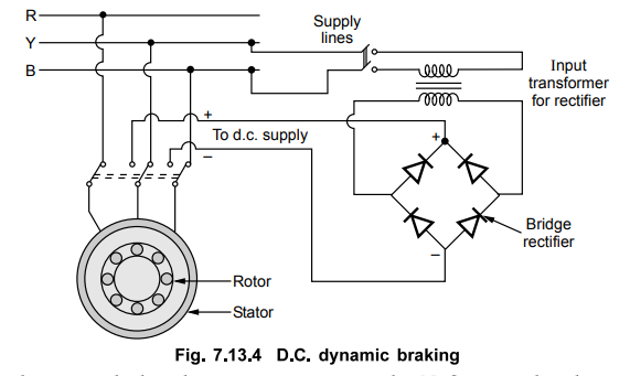
3. D.C. Dynamic Braking
A
quick stopping of an induction motor and its high inertia load can be achieved
by connecting stator terminals to a d.c. supply. Any two stator terminals can
be connected to a d.c. supply and third terminal may be kept open or may be
connected directly to other stator terminal. This is called d.c. dynamic braking.
If third terminal is kept open it is called two lead connections while if it is
shorted directly with other stator terminal it is called three lead
connections. A diode bridge can be used to get d.c. supply. The Fig. 7.13.4
shows two lead connections with a diode bridge for a d.c. dynamic braking of an
induction motor.
When
d.c. is supplied to the stator, stationary poles N, S are produced in stator.
The number of stationary poles is P for which stator winding is wound. As rotor
is rotating, rotor cuts the flux produced by the stationary poles. Thus the
a.c. voltage gets induced in the rotor. This voltage produces an a.c. current
in the rotor. The motor works as a generator and the I2 R losses are
dissipated at the expenditure of kinetic energy stored in the rotating parts.
Thus dynamic braking is achieved. When all the kinetic energy gets dissipated
as heat in the rotor, the induction motor comes to rest.
The
advantages of d.c. dynamic braking are,
1.
The heat produced is less compared to the plugging.
2.
The energy dissipated in the rotor is not dependent on the magnitude of the
d.c. current.
3.
The braking torque is proportional to the square of the d.c. current.
4.
Quick stopping of the motor is possible.
5.
The method can be used for wound rotor or squirrel cage rotor induction motors.
4. Regenerative Braking
The
input power to a three phase induction motor is given by,
Pin
= 3 Vph Iph cos ϕ
where ϕ = Angle between stator phase
voltage and phase current
This
is less than 90° for the motoring action.
If
the rotor speed is increased greater than the synchronous speed with the help
of external device, it acts as an induction generator. It converts the input
mechanical energy to an electrical energy which is given back to supply. It
delivers active power to the 3 phase line. The ϕ becomes greater than 90°. The
power flow reverses hence rotor induced e.m.f. and rotor current also reverse.
So rotor produces torque in opposite direction to achieve the braking. As the
electrical energy is given back to the lines while braking, it is called regenerative
braking. The arrangement for regenerative braking is shown in the Fig.
7.13.5.

Key Point The active power
delivered hack is proportional to the slip above the synchronous speed. The
slip is negative for such operation.
The
torque-slip characteristics for motoring and generating action is shown in the
Fig. 7.13.6

The
main advantage is that the generated power can be used for useful purposes.
While the disadvantage is that for fixed frequency supply it can be used only
for speeds above synchronous speed.
Review Questions
1. Explain the dynamic braking of three phase induction motor.
2. Discuss the plugging method used for braking of three phase
induction motor.
3. Explain the d.c. dynamic braking of three phase induction
motor.
4. Explain the regenerative braking of three phase induction
motor.
Electrical Machines II: UNIT IV: Starting and Speed Control of Three Phase Induction Motor : Tag: Engineering Electrical Machines - II : - Electric Braking of an Induction Motor
Related Topics
Related Subjects

Electrical Machines II
EE3405 Machine 2 EM 2 4th Semester EEE Dept | 2021 Regulation | 4th Semester EEE Dept 2021 Regulation