Electric Circuit Analysis: Chapter - 1: Basic Circuit Analysis - DC
Electrical quantities and Components
Electric Circuit Analysis
As pictured today, the continuous flow of electrons through a medium constitutes an electric current. Some substances such as copper and aluminium act as very good conductors of electricity and offer very little hindrance to the flow of electrons (flow of current).
ELECTRICAL QUANTITIES
As
pictured today, the continuous flow of electrons through a medium constitutes
an electric current. Some substances such as copper and aluminium act as very
good conductors of electricity and offer very little hindrance to the flow of
electrons (flow of current).
Some
other substances such as rubber and porcelain offer high resistance to the flow
of electrons and hence to the flow of current. These are known as insulators.
Materials like germanium, silicon-carbide etc., whose resistance at ordinary
temperature lies in between conductors and insulators, are called
semi-conductors.
Electric
Current (I)
The
charge of an electron is e = 1.6 × 10⁻¹⁹ Coulombs and is negative.
Electric
current is defined as rate of flow of electric charge.
i
= dq/dt ampere ….. (1)
where
q is the charge in Coulombs.
The
unit of current is the ampere, which represents one coulomb of charge
transferred in one second. The direction of current flow depends on the flow of
charge. If 'Q' coulombs of charge are continuously transferred every T seconds,
we may write equation (1) as
I
= Q/T …… (2)
Electric
Potential (E or V)
This
is generally measured between two points and its unit is the volt. If the work
done in moving a charge of one coulomb between the two points is one joule,
then we say that the potential of one point with reference to the second point
is one volt.
Vor
E= dW / dQ …… (3)
where
W is the work done in joules.
Electrical
Resistance (R)
The
resistance of a circuit is the property by which it opposes the flow of
current. This parameter, measured in Ohms, is responsible for energy
dissipation. The Ohm is defined as the resistance (at zero degree centigrade)
of a column of mercury of uniform cross-section having a length of 106.3 cm and
a mass of 14.4561 grams.
The
resistance of a conductor depends on (a) its length, (b) the cross-sectional
area, (c) the material of the conductor (d) the temperature. Usually, the
resistance is given per unit cross-section and unit length. This is called
specific resistance or resistivity of the material represented by the letter,
p. The resistivity of aluminium is 0.0283 μ Q-m while that of copper is 0.0173
μ 2-m. The resistance of a material is given by
R
= ρl / ɑ ………. (4)
where
'l' is the length and 'a' is the area of cross-section.
In
SI units, 'ρ ' is in Ohm-m, while 'l' is in m and 'a' is in sq-m
Electrical
Conductance (G)
The
reciprocal of resistance is called conductance. Its unit is Siemen and its
symbol is G.
G
= 1/R
Similarly,
the reciprocal of resistivity is called conductivity. Its symbol is ɑ.
ɑ
= 1/ρ Siemen/metre
EXAMPLE
1:
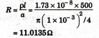
A copper wire is 500 m long and has a diameter of one mm. Find its
resistance if the resistivity of copper is 1.73 × 10⁻⁸ Ω-m.
Solution
EXAMPLE
2:
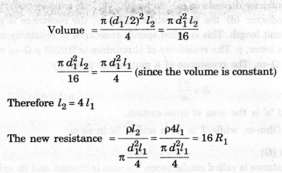
A copper wire of given length and diameter has a resistance of R Ohms. It is
drawn successfully through dies till its diameter is half the previous value.
Assuming that the resistivity remains unchanged, find the new resistance.
Solution
Let
the given length be l1 and diameter d1. Total
volume of copper in the wire
=
πd21 l1 / 4
This
remains unchanged even after passing through dies.
If
the new length is l2, (the diameter being d1 / 2 )
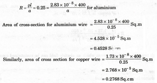
EXAMPLE
3: An aluminium wire 400 meters long has a
resistance of 0.25 Ohm. Find its area of cross-section. Find the area of cross
section required if the wire is of copper (specific resistances of copper and
aluminium are 1.73 x 10⁻⁸ and 2.83 × 10⁻⁸ Ohm-m respectively).
Solution
BASIC CIRCUIT COMPONENTS
The
three basic circuit components are
1.
Resistor
2.
Capacitor and
3.
Inductor
Resistor
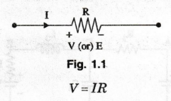
Resistor
is an electrical component made from the material which opposes the flow of
current through it. Figure 1.1 shows symbol of resistor. It is denoted as 'R'. The
unit of resistance is Ohm (Ω).
The
relation between voltage and current is given by Ohm's law.
Energy
dissipated in the resistor in the form of heat. It is given by
P
= VI = (IR)I = I2 R = V2 / R watts.
Resistor
converts amount of energy into heat during time t and it is given by
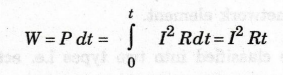
=
V.I.t joules
Capacitor
Capacitor
is a storage element which can store and deliver energy in an electric field.
The capacitor is denoted as 'C'. The unit of capacitance is Farad (F). Figure
1.2 shows the symbol of capacitor.
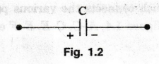
Any
two metal plates between which an electric field can be maintained constitute a
capacitor.
Inductor
Inductor
is an element in which energy can be stored in the form of electromagnetic
field. Figure 1.3 shows symbol of inductor. It is denoted as L. It is measured
in Henry (H).
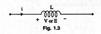
It
is like a coil wound on a magnetic core or may be air core.
Electric Circuit Analysis: Chapter - 1: Basic Circuit Analysis - DC : Tag: : Electric Circuit Analysis - Electrical quantities and Components