Electrical Machines: Unit I: b. Electromechanical Energy Conversion
Energy Flow in Electromechanical Energy Conversion Device
For any electromechanical energy conversion, there are two systems, electrical system and mechanical system. These systems are coupled through a coupling field which is mostly a magnetic one.
Energy
Flow in Electromechanical Energy Conversion Device
AU : May-03, 08, 10, 11, 15,
Dec.-09, 06
•
For any electromechanical energy conversion, there are two systems, electrical
system and mechanical system. These systems are coupled through a coupling
field which is mostly a magnetic one.
•
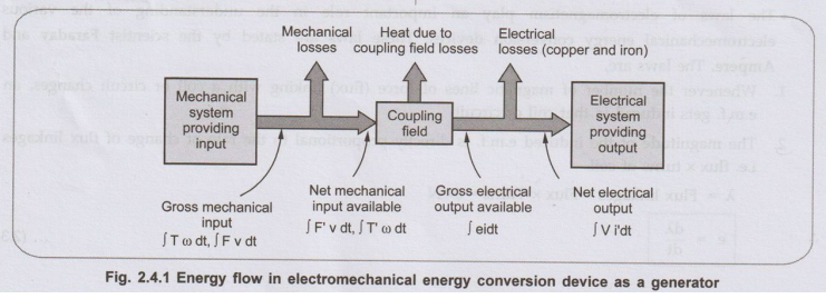
Now for a generator, input is mechanical energy but entire input cannot reach
to the coupling field for the conversion. Part of it gets lost in the form of
friction and windage losses. The available mechanical input is converted to
electrical by the device via coupling field. But net output cannot be equal to
converted electrical energy as some part of it gets lost in the form of electrical
losses such as copper (I2R) losses and core or iron losses. The Fig.
2.4.1 shows the energy flow diagram of electromechanical energy conversion
device working as a generator.
Key Point :
The heat loss due to coupling field is practically neglected and conversion
process is assumed to be ideal.
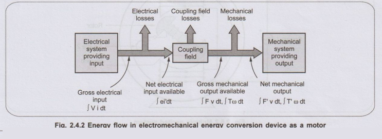
• The conversion process is reversible. For an electromechanical energy conversion device working as a motor, the net input is electrical energy. But part of this gets lost in electrical losses such as copper and iron losses. The remaining part is available to the coupling field for the conversion called net electrical input. The coupling field converts this to gross mechanical output. But entire gross mechanical output cannot be available to the load due to mechanical losses like friction and windage. Thus net mechanical output is less than the gross mechanical output. Practically conversion process is not ideal as there are coupling field losses. But from analysis point of view these losses are neglected as small and the conversion process is assumed to be ideal. The Fig. 2.4.2 shows the energy flow diagram of electromechanical energy conversion device working as a motor.
•
This energy flow is according to the energy balance equation.
Review Questions
1. Give a brief note
on flow of energy in electromechanical devices. AU : May-03, Marks 8
2. Draw and explain
the general block diagram of an electromechanical energy conversion device. AU : Dec.-06, Marks 8
3. Represent
pictorially the flow of energy in electromechanical devices for both generating
and motoring action. AU : May-08, 10, 11,
Dec.-09, Marks 8
4.Explain the methods
of energy conversion via electric field, with examples of electrical machines. AU : May-15, Marks 16
Electrical Machines: Unit I: b. Electromechanical Energy Conversion : Tag: : - Energy Flow in Electromechanical Energy Conversion Device
Related Topics
Related Subjects

Electrical Machines I
EE3303 EM 1 3rd Semester EEE Dept | 2021 Regulation | 3rd Semester EEE Dept 2021 Regulation