Electrical Machines II: UNIT III: a. Three Phase Induction Motor
Equivalent Circuit of Induction Motor
We have already seen that the induction motor can be treated as generalized transformer.
Equivalent Circuit of Induction Motor AU : May-06, 09, 12,
13, 16,18, Oct.-97, Dec -05, 07, 08, 11, 12, 16
We
have already seen that the induction motor can be treated as generalized
transformer. Transformer works on the principle of electromagnetic induction.
The induction motor also works on the same principle. The energy transfer from
stator to rotor of the induction motor takes place entirely with the help of a
flux mutually linking the two. Thus stator acts as a primary while the rotor
acts as a rotating secondary when induction motor is treated as a transformer.
If E1 = Induced voltage in stator
per phase
E2
= Rotor induced e.m.f. per phase on standstill
K
= Rotor turns / Stator turns
then K = E2 / E1
Thus
if V1 is the supply voltage per phase to stator, it produces the
flux which links with both stator and rotor. Due to self induction, E1 is
the induced e.m.f. in stator per phase while E2 is the induced
e.m.f. in rotor due to mutual induction, at standstill. In running condition
the induced e.m.f. in rotor becomes E2r which is sE2.
Now E2r = Rotor induced e.m.f. in
running condition per phase
R2
= Rotor resistance per phase
X2r
= Rotor reactance per phase in running condition
R1
= Stator resistance per phase
X1
= Stator reactance per phase
So
induction motor can be represented as a transformer as shown in the Fig.
5.18.1.
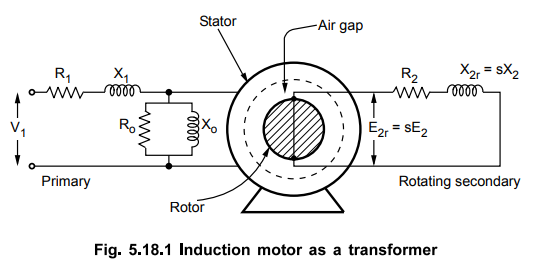
When
induction motor is on no load, it draws a current from the supply to produce
the flux in air gap and to supply iron losses.
This
current Io has two components.
1.
Ic = Active component which supplies no load losses
2.
Im = Magnetising component which sets up flux in core and air gap
These
two currents give us the elements of an exciting branch as,
Ro
= Representing no load losses = V1 / Ic
And
Xo = Representing flux set up = V1 / Im
Thus, 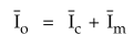
The
equivalent circuit of induction motor thus can be represented as shown in the
Fig. 5.18.2

The
stator and rotor sides are shown separated by an air gap.
I2r
= Rotor current in running condition 
It
is important to note that as load on the motor changes, the motor speed
changes. Thus slip changes. As slip changes the reactance X2r
changes. Hence X2r = sX2 is shown variable
Representation
of rotor impedance :
It
is known that, 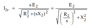
So
it can be assumed that equivalent rotor circuit in the running condition has
fixed reactance X2, fixed voltage E2 but a variable
resistance R2/s, as indicated in the above equation.
Now 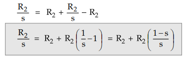
So
the variable rotor resistance R2/s has two parts,
1.
Rotor resistance R2 itself which represents copper loss.
2.
R2 (1 - s)/s which represents load resistance RL. So it
is electrical equivalent of mechanical load on the motor.
Key Point Thus mechanical
load on the motor is represented by the pure resistance of value R2
(1 - s) /s.
So
rotor equivalent circuit can be shown as,

Now
let us obtain equivalent circuit referred to stator side.
Equivalent
circuit referred to stator :
Transfer
all the rotor parameters to stator,
K
= E2 / E1 = Transformation ratio
E2
= E2 / K
The
rotor current I2r has its reflected component on the stator side which is I2r.

Thus
RL is reflected mechanical load on stator.
So
equivalent circuit referred to stator can be shown as in the Fig. 5.18.4.

The
resistance R'2 (l - s)/s = R'L is fictitious resistance representing
the mechanical load on the motor.
1. Approximate Equivalent Circuit
Similar
to the transformer the equivalent circuit can be modified by shifting the
exciting circuit (Ro and Xo) purely across the supply, to
the left of R1 and X1. Due to this, we are neglecting the
drop across R1 and X1 due to Io , which is
very small. Hence the circuit is called approximate equivalent circuit. The
circuit is shown in the Fig. 5.18.5.

Now
the resistances R1 and R2 while reactance X1
and X2 can be combined. So we
Rle
= Equivalent resistance referred to stator = R1 + R2
Xle
= Equivalent reactance referred to stator = X1 + X2

Thus
the equivalent circuit can be shown in the Fig. 5.18.6.

2. Power Equations from Equivalent Circuit
With
reference to approximate equivalent circuit shown in the Fig. 5.18.6, we can
write various power equations as,
Pin
= Input power = 3 V1 I1 cos ϕ
Where
V1 = Stator voltage per phase
I1
= Current drawn by stator per phase
cos
ϕ = Power factor of stator
Stator
core loss = Im2 Ro
Stator
copper loss = 3 I12 R1
where
R1 = Stator resistance per phase
P2
= Rotor input = 3(I2r)2 R2 / s
Pc
= Rotor copper loss = 3(I2r)2 R2
Then
Pc = s P2
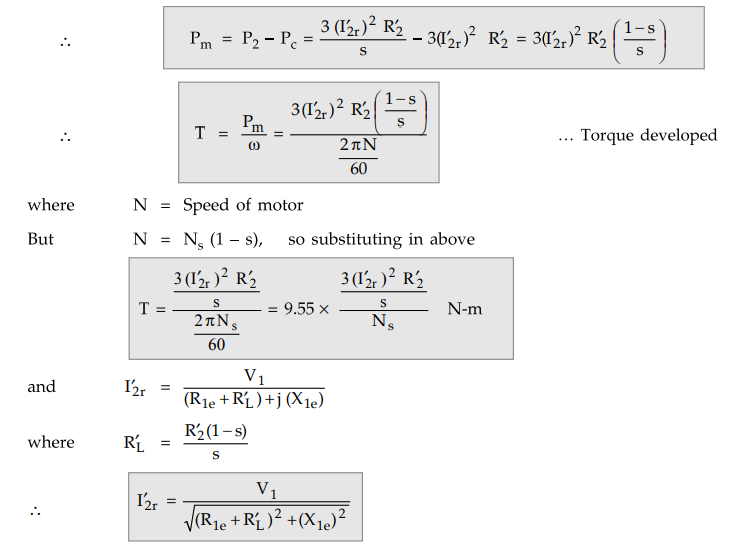
Pm
= Gross mechanical power developed
Key Point Remember that in
all the above formulae all the values are per phase values.
3. Maximum Power Output
Consider
the approximate equivalent circuit as shown in the Fie. 5.18.7.

In
this circuit, the exciting current Io is neglected hence the exciting no load
branch is not shown.
I1
= I2r
The
total impedance is given by,
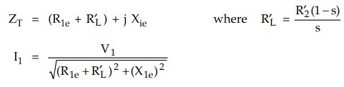
The
power supplied to the load i.e. Pout per phase is,
Per
phase Pout = I12 R'L watts per
phase
Total
Pout = 3 I21 R'L

To
obtain maximum output power, differentiate the equation of total Pout
with respect to variable RL and equate to zero.
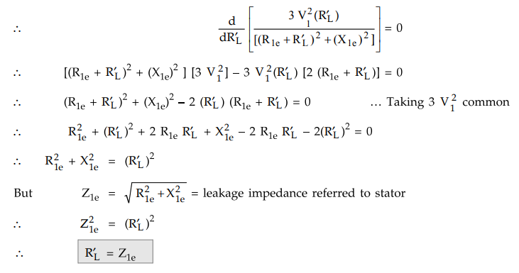
Thus
the mechanical load on the induction motor should be such that the equivalent
load resistance referred to stator is equal to the total leakage impedance of
motor referred to stator.

Expression
for maximum Pout : Using the condition obtained in expression of
total Pout , we can get maximum Pout

4. Maximum Torque
In
case of induction motor, the speed of the motor decreases with increase in
load. Thus the maximum power output is not obtained at a slip which corresponds
to maximum torque. In the previous section we have seen the condition for
maximum power output. In this section we will find the condition which gives
maximum torque.
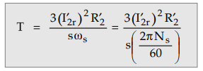
The
expression for torque is given by,
The condition for maximum torque can be. obtained from maximum power transfer
theorem. When (I’2r)2 R’2 / is maximum
consider the approximate equivalent circuit of induction motor as shown in the
Fig. 5.18.8.
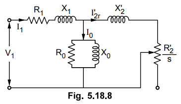
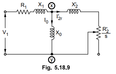
The
value of R0 is assumed to be negligible. Hence the circuit will be
reduced as shown in the Fig. 5.18.9.
The
The venin's equivalent circuit for the V1 above network is shown in the Fig.
5.18.10 across the terminals x and y.
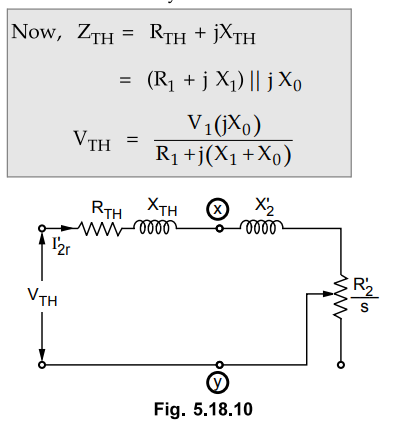
The
mechanical torque developed by rotor is maximum if there is maximum power
transfer to the resistor R’2 / s. This takes place when R’2
/ s equals to impedance looking back into the supply source.

From
the above expression, it can be seen that the maximum torque is independent of
rotor resistance R2.
5. Synchronous Watt
The
torque produced in the induction motor is given by,

Thus
torque is directly proportional to the rotor input. By defining new unit of
torque which is synchronous watt we can write,
T
= P2 synchronous-watts
If
torque is given in synchronous-watts then it can be obtained in N-m as,

Key Point Unit synchronous
watt can be defined as the torque developed by the motor such that the power
input to the rotor across the air gap is 1 W while running at synchronous
speed.
Example
5.18.1 The following
data refers to a 12 pole, 420 V, 50 Hz, three phase mesh connected induction
motor :
r1
= 2.95 Ω, x1 = 6.82 Ω, r2 = 2.08 Ω, x2 = 4.11
Ω, per phase.
On
no load, the line value of magnetizing current is 6.7 A and the total core loss
is 269 W. Determine the power factor, input current, equivalent rotor current
and torque developed by the motor at a slip of 3 % using exact equivalent
circuit. Determine the maximum torque developed and the corresponding speed. AU
: Dec.- 08, Marks 16
Solution
:
On no load, the equivalent circuit is as shown in the Fig. 5.18.11.
Im(Line)
= 6.7 A
As
motor is delta connected,

The
exact equivalent circuit is shown is the Fig. 5.18.12.

The
equivalent rotor current I2r can be obtained by using current
distribution rule in parallel circuit as,

The
torque developed is,
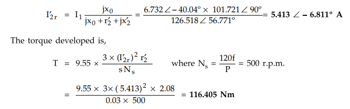
To
find the maximum torque Tm, first calculate Thevenin's equivalent RTH
and X TH

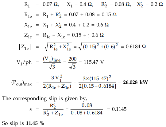
Example
5.18.2 A 3 phase, 200 V, induction motor has stator
impedance of (0.07 +j 0.4) Ω /ph while equivalent rotor impedance referred to
stator is (0.08+j 0.2) Ω /ph. Neglecting no load current, calculate the maximum
mechanical power output and the slip corresponding to maximum output condition.
Assume star connected stator.
Solution
:
The given values are
Example
5.18.3 A 3 phase, star connected 400 V, 50 Hz, 4 pole
induction motor has the following per phase parameters in ohms, referred to the
stator.
R1
= 0.15, X1 = 0.45, R'2 = 0.12, X’2 = 0.45, Xm
= 28.5
Compute
the stator current and power factor when the motor is operated at rated voltage
and frequency with s = 0.04.
Solution
:
The equivalent circuit referred to stator is shown in the Fig. 5.18.13.

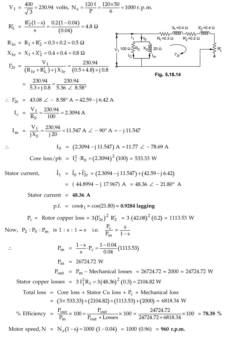
Example
5.18.4 A 400 V, 50 Hz, 3 phase, 6 pole star connected
induction motor has the following values for the various parameters of its
equivalent circuit.
Stator
impedance = (0.3 + j 0.4) Ω
Equivalent
rotor impedance = (0.2 + j 0.4) Ω
Magnetizing
reactance = 20 Ω
Resistance
to account fore core loss = 100 Ω
Using
the approximate equivalent circuit calculate for a slip of 4 percent a) Motor
speed b) Stator current c) Power factor d) Motor output and efficiency. Assume
stator losses, mechanical losses to be 2 kW each.
Solution
The
given values are
R1
= 0.3 Ω , X1 =
0.4 Ω Mechanical losses = 2 kW
R2
= 0.2 Ω , X’2 =
0.4 Ω
Xo
= 20 Ω, s = 0.04
Ro
= 100 Ω, Stator loss = 2
kW
The
approximate equivalent circuit is shown in Fig. 5.18.14.
Example
5.18.5 A 4 pole, 50 Hz, 3 phase induction motor, when
loaded has total rotor input of 3000 W. Determine the torque developed in i)
N-m and ii) Synchronous watts.
Solution
: The
given values are,

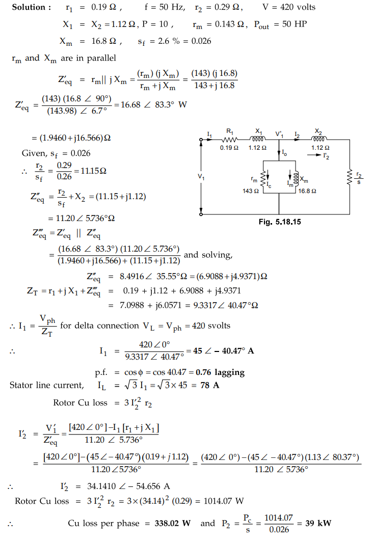
Example
5.18.6 A 50 HP, 420 V, 3 phase, 10 pole, delta connected
induction motor has r1 - 0.19 ohm, r2 - 0.29 ohm, X1 = X2
= 1.12 ohm rm - 143 ohm, Xm - 16.8 ohm. Full load slip - 2.6 %. Use
exact equivalent circuit and calculate i) Rotor Input ii) Rotor Copper loss per
phase iii) Stators current and power factor.
Solution
:
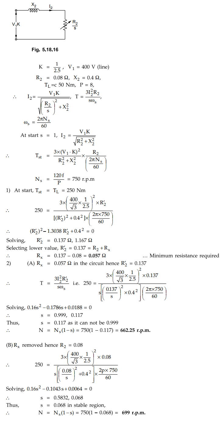
Example
5.18.7 A 3 phase, 25 kW, 400 V, 50 Hz, 8-pole induction
motor has rotor resistance of 0.08 ohm and standstill resistance of 0.4 ohm.
The effective stator/rotor turn ratio is 2.5. The motor is to drive a
constant-torque load of 250 N-m . Neglect stator impedance : 1) Calculate the
minimum resistance to be added in rotor circuit for the motor to start up on
load. 2) At what speed would the motor run, if the added rotor resistance is
(A) left in the circuit, and (B) subsequently short circuited.
Solution
:
Neglecting
stator impedance, the equivalent circuit on rotor side is shown in the Fig.
5.18.6
Examples
for Practice
Example
5.18.8 A three phase, star connected 400 volt, 50 Hz, 4
pole induction motor has following parameters referred to stator ;
r1
= 0.15 ohm, x1= 0.44 ohm,
r'2
= 0.12 ohm, x'2 = 0.44 ohm,
xm
- 30 ohm neglect core loss resistance (rc), find stator current,
power factor at rated voltage and slip of 4 %.
[Ans.:
73.045 Z- 21.42° A, 0.9309 lagging]
Example
5.18.9 A 440 V, 50 Hz, 4-pole, 3-phase delta connected
induction motor has a leakage impedance of (0.3 + 7 5.5 + 0.25 /s) ohm / phase
(delta phase) referred to the stator. The stator to rotor voltage ratio is 2.5.
Determine the external resistance to be inserted in each star-phase of the
rotor winding such that the motor develops a gross torque of 150 N-m at a speed
of 1250 r.p.m. UPTU : 2006-07
[Ans.:
Rx= 0.189 Ω/ph]
Example
5.18.10 Consider thr equivalent circuit diagram
of 3 Y- connected, 440 V, shown Fig.5.18.17:
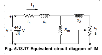
Where
r1 = 0.209Ω x1 = 0.503 Ω xm = 13.25 Ω r2
= 0.209 Ω x2 = 0.144Ω
i)
Determine the stator current and power factor (motor runs at Nr =
1460 r.p.m.)
ii)
Determine the air gap power and rotor copper losses (motor runs at Nr = 1450 r.p.m.)
iii)
What is the value of motor speed at which it takes 30 ampere current at 0.8
p.f. lagging from supply mains ?
iv)
What is value of slip when motor runs at Nr = 1480 rpm. UPTU
: 2011-12
[Ans.:
i) 35.233∠-33.573°A,0.8331
lagging, ii) 867.247 W, 26 kW, iii) 1467.75 r.p.m., iv) 1.333 %]
Example
5.18.11 A 4 pole, 50 Hz, 3 phase induction motor, when
loaded has total rotor input of 3000 W. Determine the torque developed in i)
N-m and ii) Synchronous watts.
[Ans.:
i) 19.098 N-m, ii) 3000 syn-watt]
Example
5.18.12 For a 3ϕ IMs, show that :

Example
5.18.13 A 400 V, 1450 r.p.m., 50 Hz, wound rotor
induction motor has the following circuit modal parameters.
R1
= 0.3 Ω, R2 = 0.25 Ω, X1 = X2= 0.6 Ω, Xm
= 35 Ω,
Rotational
loss = 1500 W.
i)
Calculate the starting torque and current when the motor is started direct on
full voltage.
ii)
Find the slip for maximum torque and the value of maximum torque. VTU : Feb -06
[Ans.:
176.6407∠-
65.528 ° A, 143.9 Nm, 0.2041 i.e. 20.41 %, 324.922 Nm]
Example
5.18.14 The following data refers to a 12 pole, 420 V,
50 Hz, three phase mesh connected induction motor :
r1
= 2.95 Ω, x1 = 6.82Ω
, r'2 = 2.08 Ω, x'2 = 4.11Ω, per phase.
On
no load, the line value of magnetizing current is 6.7 A and the total core loss
is 269 W. Determine the power factor, input current, equivalent rotor current
and torque developed by the motor at a slip of 3 % using exact equivalent
circuit. Determine the maximum torque developed and the corresponding speed.
[Ans.:
0.7655 lagging, 6.732 ∠-40M°
A, 5.413 ∠-
6.811“ A, 116.405 Nm, 331.35 Nm, 404.4 r.p.m.]
Review Questions
1. Develop an equivalent circuit of a 3 phase induction motor.
What do the various paramenters represent ? Represent the approximate
equivalent circuit and state its significance.
AU : May-06, 16,18, Dec.-05, 07, 11,
12, Marks 8
2. Starting from the equivalent circuit, derive the various
power equations of an induction motor. AV : May-12, Marks 8
3. Show how a 3 phase induction motor can be represented by an
approximate equivalent circuit. AU : May-13, Dec.-16, Marks 8
Electrical Machines II: UNIT III: a. Three Phase Induction Motor : Tag: Engineering Electrical Machines - II : - Equivalent Circuit of Induction Motor
Related Topics
Related Subjects

Electrical Machines II
EE3405 Machine 2 EM 2 4th Semester EEE Dept | 2021 Regulation | 4th Semester EEE Dept 2021 Regulation