Electrical Machines II: UNIT V: a. Single Phase Induction Motors
Equivalent Circuit of Single Phase Induction Motor
The double revolving field theory can be effectively used to obtain the equivalent circuit of a single phase induction motor.
Equivalent Circuit of Single Phase Induction Motor AU
: April-01, Dec.-05, 15, 17, May-17
The
double revolving field theory can be effectively used to obtain the equivalent
circuit of a single phase induction motor. The method consists of determining
the values of both the fields clockwise and anticlockwise at any given slip.
When the two fields are known, the torque produced by each can be obtained. The
difference between these two torques is the net torque acting on the rotor.
Imagine
that the single phase induction motor is made up of one stator winding and two
imaginary rotor windings. One rotor is rotating in forward direction i.e. in
the direction of rotating magnetic field with slip s while other is rotating in
backward direction i.e. in direction of oppositely directed rotating magnetic
field with slip 2 - s.
To
develop the equivalent circuit, let us assume initially that the core loss is
absent.
1. Without Core Loss
Let
the stator impedance be Z Ω
Z
= R1 + j X1
where
R1 = Stator resistance
X1
= Stator reactance
and
X2 = Rotor reactance referred to stator
R2
= Rotor resistance referred to stator
Hence
the impedance of each rotor is r2 + j x2 where
X2
= X2 / 2
The
resistance of forward field rotor is r2 / s while the resistance of
backward field rotor is r2 / (2 - s ) The r9 r2 value is
half of the actual rotor resistance referred to stator.
As
the core loss is neglected, R0 is not existing in the equivalent
circuit. The X0 is half of the actual magnetising reactance of the
motor. So the equivalent circuit referred to stator is shown in the Fig. 8.9.1.
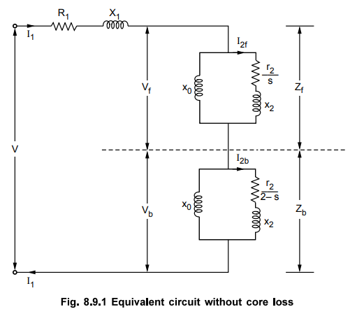
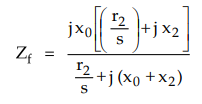
Now
the impedance of the forward field rotor is Zf which is parallel
combination of (0 + j X0) and (r2/s) + j x2.
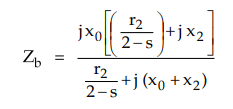
While
the impedance of the backward field rotor is Zb which is parallel
combination of (0 + j x0) and (r2 2-s ) + j x2.
Under
standstill condition, s = 1 and 2 - s = 1. Hence Zf = Zb
and Vf = Vb. But in the running condition, Vf
becomes almost 90 to 95 % of the applied voltage.
Zeq
= Z1 + Zf + Zb = Equivalent impedance
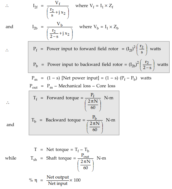
Let
I2f = Current through forward rotor referred to stator
and
I2b = Current through backward rotor referred to stator
2. With Core Loss
If
core loss is to be considered then it is necessary to connect a resistance r0
in parallel with x0, in an exciting branch of each rotor r0
is half the value of actual core loss resistance. Thus the equivalent circuit
with core loss can be shown as in the Fig. 8.9.2.

Let
Zof = Equivalent impendanve of exciting branch in forward rotor
=
r0 || (j x0 )
And
Zob = Equivalent impendanve
of exciting branch in backward rotor
=
r0 || (j x0 )
Zf
= Zof || (r2 / s + j x2 )
All
other expressions remain same as stated earlier in case of equivalent circuit
without core loss.
Example
8.9.1 A 600 W, 230 V, 50 Hz, 6 pole, single phase
induction motor has following parameters :
Resistance
of main stator winding = 3 Ω
Reactance
of main stator winding = 4.15 Ω
Reactance
of magnetising branch referred to stator = 107 Ω
Rotor
resistance referred to stator at standstill
= 6.2 Ω
Rotor
reactance referred to stator at standstill = 2.2 Ω
The
core losses are 75 W while mechanical losses are 25 W. The motor is operating
with 5 % slip. Calculate,
i)
Input current ii) Power factor iii)
Gross power iv) Shaft power v) Efficiency.
Solution
:
The
given values are,
Example
8.9.2 A 220 V, 50 Hz, 6 pole single phase induction
motor has the following parameters V1 = 3.04 Ω ,X1 = 4.2 Ω, Xm = 105.6 Ω, r2 =
6.26 Ω, X'2 = 2.12 Ω. It is operating at 5 %. Find the
forward, backward and net torque in synchronous watts. AU : April-01, Marks 10
Solution
:

Example
8.9.3 A 2 pole 50 Hz single phase induction motor has
an effective rotor resistance and leakage reactance of 05 Ω each. If it is
running at 2600 r.p.m. Find
i)
Frequencies of rotor current components.
ii)
Relative magnitudes of forward and backward fluxes. Neglect magnetizing current
and stator impedance.
Solution
:
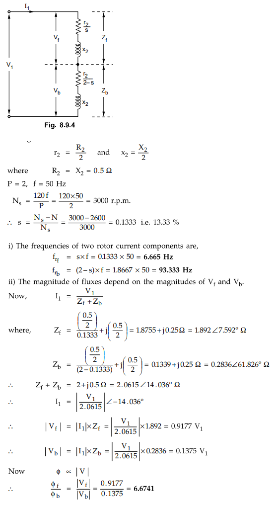
Neglecting
magnetizing current and stator impedance, the equivalent circuit is shown in
the Fig. 8.9.4.
Examples
for Practice
Example
8.9.4 A 230 V, 50 Hz, 4-pole single-phase induction
motor has the following equivalent circuit impedances.
Rlm
= 2.2 Ω, R'2 = 4.5 Ω
Xlm
= 3.1 Ω, X'2 = 2.6 Ω, Xm = 80 Ω
Friction,
windage and core loss = 40 W
For
a slip of 0.03 pu, calculate i) Input current ii) Power factor iii) Developed
power iv) Output power v) Efficiency.
[Ans.: i) 5.684 ∠- 6096, ii)
0.4854 lagging, iii) 479.43 W, iv) 439.43 W, v) 634.5731 W, % n = 69.248 %]
Example
8.9.5 The constants of a quarter H.P., 230 V, 50 Hz, 4
pole single phase induction motor are as follows : stator resistance - 10 Ω ,
stator reactance = 12.8 Ω, magnetizing reactance = 258 Ω , rotor resistance
referred to stator - 11.65 Ω .
Rotor
reactance referred, to stator - 12.8 Ω .
The
total load is such that the machine runs at 3 % slip, when the voltage is at
210 V. The iron losses are 35.5 W at 210 V. If the mechanical losses are 7 W,
calculate,
a)
Input current b) Power developed c) Shaft power d) Efficiency.
[Ans.:
a) 1.8585 ∠-
53.65° A, b) 166.72 W, c) 159.72, d)% ƞ = 63.04 %]
Example
8.9.6 A 220 V, 6-pole, 50 Hz single winding single
phase induction motor has the following equivalent circuit parameters as
referred to the stator Rlm = 3 Ω
Rlm
= 5 Ω Xlm = 5 Ω
R2
= 1.5 Ω X2 = 2 Ω
Neglect
the magnetizing current, when the motor runs at 97 % of the synchronous speed,
compute the ratio Emf/Emb and ratio Tf/ Tb'.
[Ans.:Emf
/ Emb = 23.38, Tf/ Tb'= 65.668]
Example
8.9.7 A 125 W, 4 pole 110 V, 50 Hz single phase
induction motor delivers rated output at a slip of 6 %. The copper loss at full
load is 25 watts. Calculate the full load efficiency and the rotor copper loss
caused by the backward field. Rotational losses may be assumed to be 25 watts.
Neglect stator copper loss.
[Ans.:
% ƞ = 78.33 %, 14.96 W]
Review Questions
1. Draw and explain the equivalent circuit diagram of a single
phase induction motor.
2. Develop the equivalent circuit of a single phase induction
motor.
Electrical Machines II: UNIT V: a. Single Phase Induction Motors : Tag: Engineering Electrical Machines - II : - Equivalent Circuit of Single Phase Induction Motor
Related Topics
Related Subjects

Electrical Machines II
EE3405 Machine 2 EM 2 4th Semester EEE Dept | 2021 Regulation | 4th Semester EEE Dept 2021 Regulation