Electrical Machines: Unit IV: Single Phase Transformer
Equivalent Circuit of Single Phase Transformer
• The term equivalent circuit of a machine means the combination of fixed and variable resistances and reactances, which exactly simulates performance and working of the machine.
Equivalent
Circuit of Transformer
AU : May-03,04,09,10,
Dec.-04,08,09,11,12
•
The term equivalent circuit of a machine means the combination of fixed and
variable resistances and reactances, which exactly simulates performance and
working of the machine.
•
For a transformer, no load primary current lo has two components,
Im
= I0 sin ϕ0 =
Magnetising component
Ic
= I0 cos ϕ0 = Active component
•
Im produces the flux and is assumed to flow through reactance X0
called no load reactance while Ic is active component representing
core losses hence is assumed to flow through the resistance R0.
Hence equivalent circuit on no load can be shown as in the Fig. 6.13.1. This
circuit consisting of R0 and X0 in parallel is called
exciting circuit. From the equivalent circuit we can write,
R0
= V1 / Ic and X0 = V1 / Im

•
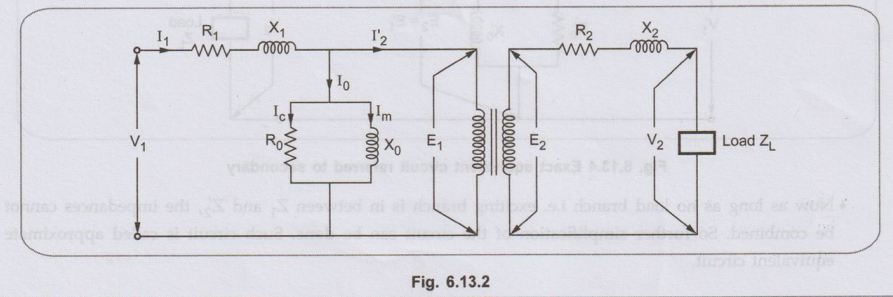
When the load is connected to the transformer then secondary current I2
flows. This causes voltage drop across R2 and X2. Due to I2,
primary draws an additional current
•I'2
= I2 / K. Now I1 is the phasor addition of I0
and I'2. This I1 causes the voltage drop across primary
resistance R1 and reactance X1.
•
Hence the equivalent circuit can be shown as in the Fig. 6.13.2.
•
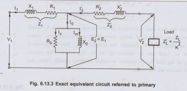
But in the equivalent circuit, windings are not shown and it is further
simplified by transferring all the values to the primary or secondary. This
makes the transformer calculations much easy.
So
transferring secondary parameters to primary we get,

While
transferring the values remember the rule that
Low
voltage winding → High current → Low impedance
High
voltage winding → Low current → High impedance
•
Thus the exact equivalent circuit referred to primary can be shown as in the
Fig. 6.13.3.
•
Similarly all the primary value can be referred to secondary and we can obtain
the equivalent circuit referred to secondary.

Similarly
the exciting circuit parameters also gets transferred to secondary as R'0
and X'0. The circuit is gris shown in the Fig. 6.13.4.

•
Now as long as no load branch i.e. exciting branch is in between Z1
and Z'2, the impedances cannot be combined. So further simplification
of the circuit can be done. Such circuit is called approximate equivalent
circuit.
1. Approximate Equivalent Circuit
•
To get approximate equivalent circuit, shift the no load branch containing R0
and X0 to the left of R1 and X1. By doing this
we are creating an error that the drop across R1 and X1
due to Io is neglected. Hence such is equivalent circuit is called approximate
equivalent circuit.
•
So approximate equivalent circuit referred primary can be as shown in the Fig.
6.13.5.

In
this circuit now R1 and R'2 can be combined to get
equivalent resistance referred to primary R1e discussed earlier.
Similarly X1 and X2 can combined to get X1e.
And equivalent circuit can be simplified as shown in the Fig. 6.13.6.

•
In the similar fashion, the approximate equivalent circuit referred to
secondary also can be obtained.
Review Questions
1. Explain in detail
step by step the procedure to draw the equivalent circuit of transformer. AU: May-03, Dec.-12,
Marks 8
2. Derive the
equivalent circuit of a single phase two winding transformer. AU May-04, 09, 10,
Dec.-04, 08, 09, 11, Marks 8
Electrical Machines: Unit IV: Single Phase Transformer : Tag: : - Equivalent Circuit of Single Phase Transformer
Related Topics
Related Subjects

Electrical Machines I
EE3303 EM 1 3rd Semester EEE Dept | 2021 Regulation | 3rd Semester EEE Dept 2021 Regulation