Digital Logic Circuits: Unit I: (a) Number Systems
Error Detection and Correction Codes
Number Systems
• When the digital information in the binary form is transmitted from one circuit or system to another circuit or system an error may occur. This means a signal corresponding to 0 may change to 1 or vice-versa due to presence of noise.
Error Detection and Correction Codes
•
When the digital information in the binary form is transmitted from one circuit
or system to another circuit or system an error may occur. This means a signal
corresponding to 0 may change to 1 or vice-versa due to presence of noise. To
maintain the data integrity between transmitter and receiver, extra bit or more
than one bit are added in the data. These extra bits allow the detection and
sometimes correction of error in the data. The data along with the extra
bit/bits forms the code. Codes which allow only error detection are called
error detecting codes and codes which allow error detection and correction are
called error detecting and correcting codes.
1. Parity Bit
•
A parity bit is used for the purpose of detecting errors during transmission of
binary information. A parity bit is an extra bit included with a binary message
to make the number of Is either odd or even. The message, including the parity
bit is transmitted and then checked at the receiving end for errors. An error
is detected if the checked parity does not correspond with the one transmitted.
The circuit that generates the parity bit in the transmitter is called a parity
generator and the circuit that checks the parity in the receiver is called a
parity checker.
•
In even parity the added parity bit will make the total number of Is an even
amount. In odd parity the added parity bit will make the total number of Is an
odd amount.
•
Table 1.8.1 shows the 3-bit message with even parity and odd parity.

Ex.
1.8.1 Write a ASCII code for the decimal digit 9 with an even parity. Place
parity bit in the most significant position.
Sol.
:
The 7-bit ASCII code for the decimal digit 9 is 0111001. This requires the
addition of a 0 in the most significant place to give even parity as shown.
Added
parity bit → 00111001
Ex.
1.8.2 Write a ASCII code for the alphabet A' with an odd parity. Place parity
bit in the most significant position.
Sol.
:
The 7-bit ASCII code for the alphabet 'A' is 1000001. This requires the
addition of a 1 in the most significant place to give odd parity, as shown.
Added
parity bit → 11000001
At
the receiving end, message with parity bit is received. Every time it is
checked for parity. When parity error is detected, receiver requests for
transmitter to re-transmit the message.
Ex.
1.8.3 The received code is 1000 0001. Check whether code is correctly received
or not if odd parity is used.
Sol.
:
The received code has even parity hence the code is not received correctly.
More
about parity error detection
As
a general rule in a digital system where the transmission system is relatively
short, it may be assumed that the probability of a single-bit error is small
and that of a double-bit error and higher order errors is extremely small. The
parity error detection system just described detects any odd number of errors.
However, it cannot detect an even number of error because such errors will not
destroy the parity of the transmitted group of bits.
2. Block Parity
•
When several binary words are transmitted or received in succession, the
resulting collection of bits can be regarded as a block of data, having rows
and columns. For example, four eight bit words in succession form an 4x8 block.
Parity bits can then be assigned to both rows and columns, as shown in Fig.
1.8.1 (a). This scheme is known as block parity. It makes it possible to
correct any single error occurring in a data word and to detect any two errors
in a word. Let us see how we can do this.
•
As shown in the Fig. 1.8.1 (b), the third bit in the second data word is in
error, having been changed from a 0 to a 1. The number of Is in the third
column is odd, and the number of Is in the second row is also odd. Therefore,
the even parity bits in the third column and second row both detect the error
and we know that the third bit from the second word must be changed from a 1 to
a 0. Fig. 1.8.1 (c) shows two errors in the first word. Since the total number
of Is is still even, the parity bit in the first row does not detect error.
However, the parity bits in the 3rd and 4th columns do detect the error. In
this case, we are not able to correct the error because there is no information
revealing the row where the errors occurred.

3. Hamming Code
•
Hamming code not only provides the detection of a bit error, but also
identifies which bit is in error so that it can be corrected. Thus Hamming code
is called error detecting and correcting code. The code uses a number of parity
bits (dependent on the number of information bits) located at certain positions
in the code group. Follows sections describe how Hamming code can be
constructed for single error correction.
Number
of Parity Bits
•
As mentioned earlier, number of parity bits depend on the number of information
bits. If the number of information bits is designed x, then the number of
parity bits, P is determined by the following relationship :
2P
≥ x + P + 1 ...(1.8.1)
For
example, if we have four information bit, i.e. x = 4, then P is found by trial
and error using equation 1. Let P = 2. Then
2
P = 2 2 = 4
and
x
+ P + 1 = 4 + 2 + 1 = 7
Since
2P must be equal to or greater than x + P + 1, the relationship in
equation
(1.8.1) is not satisfied. Hence we have to try with next value of P. Let P = 3.
Then
2
P = 2 3 = 8
and
x
+ P + 1 = 4 + 3 + 1= 8
•
This value of P satisfies the relationship given is equation (1.8.1), and
therefore we can say that three parity bits are required to provide single
error correction for four information bits.
Locations
of the Parity Bits in the Code
•
Now we know that how to calculate the number of parity bits required to provide
single error correction for given number of information bits. In our example we
have four information bits and three parity bits. Therefore, the code is of
seven bits. The right-most bit is designated bit 1, the next bit is bit 2, and
so on, as shown below :
Bit
7, Bit 6, Bit 5, Bit 4, Bit 3, Bit 2, Bit 1
•
The parity bits are located in the positions that are numbered corresponding to
ascending powers of two (1, 2, 4, 8 ...). Therefore, for 7 - bit code,
locations for parity bits and information bit are as shown below :
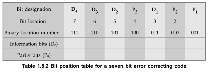
D4,D3,D2,P3,D1,P2,P1
where
symbol Pn designates a particular parity bit, Dn
designates a particular information bit.
Assigning
Values to Parity Bits
•
Now we know the format of the code. Let us see how to determine 1 or 0 value to
each parity bit. In Hamming code, each parity bit provides a check on certain
other bits in the total code, therefore, we must know the value of these others
in order to assign the parity bit value. To do this, we must write the binary
number for each decimal location number as shown in the third row of Table 1.8.2.
Assignment
of P1 :
•
Looking at the Table 1.8.2 we can see that the binary location number of parity
bit P-[ has a 1 for its right-most digit. This parity bit checks all bit
locations, including itself, that have Is in the same location in the binary
location numbers. Therefore, parity bit Px checks bit locations 1, 3, 5 and 7,
and assigns P1 according to even or odd parity. For even parity
Hamming code, it assigns P1 such that bit locations 1, 3, 5, and 7 will have
even parity.
Assignment
of P2 :
•
Looking at the Table 1.8.2 we can see that the binary location number of parity
bit P2 has a 1 for its middle bit. This parity bit checks all bit locations,
including itself, that have Is in the middle bit. Therefore, parity bit P2
checks bit locations 2, 3, 6 and 7 and assigns P2 according to even
or odd parity.
Assignment
of P3 :
•
Looking at the Table 1.8.2 we can see that the binary location number of parity
bit P3 has a 1 for its left-most digit. This parity bit checks all bit
locations, including itself, that have Is in the left-most bit. Therefore,
parity bit P3 checks bit locations 4, 5, 6 and 7 and assigns P3
according to even and odd parity.
Ex.
1.8.4 Encode the binary word 1011 into seven bit even parity Hamming code.
Sol.
:
Step
1 :
Find the number of parity bits required. Let P = 3, then
2P
= 2 3 = 8
x
+ P + 1 = 4 + 3 + 1= 8
Three
parity bits are sufficient.
Total
code bits = 4 + 3 = 7
Step
2 :
Construct a bit location table

Step
3 :
Determine the parity bits
For
P1 : Bit locations
3, 5 and 7 have three Is and therefore to
have an even parity P1 must be 1.
For
P2 : Bit locations 3, 6
and 7 have two Is and therefore to have an
even parity P2 must be 0.
For
P3 : Bit locations
5, 6 and 7 two Is and therefore to have an
even parity P3
must be 0.
Step
4 :
Enter the parity bits into the table to form a seven bit Hamming code =1010101.
Ex.
1.8.5 Determine the single error-correcting code for the information code 1 0 1
1 1 for odd parity.
Sol.
:
Step
1 :
Find the number of parity bits required. Let P = 3.
Then 2P = 23 = 8
x
+ P + 1 = 5 + 3 + l = 9
This
will not work. Try P = 4. Then
2P
= 24 = 16
x
+ P + 1 = 5 + 4 + 1 = 10
Equation
(1.8.1) is satisfied and hence four bits are sufficient.
Total
code bit = 5 + 4 = 9
Step
2 :
Construct a bit location table

Step
3 :
Determine the Parity Bits
For
P1 : Bit locations
3, 5, 7 and 9 have three Is and therefore
to have odd parity P1 must be 0.
For
P2 : Bit locations
3, 6, 7 have two Is and therefore to have
an odd parity P2 must be 1.
For
P3 : Bit locations
5, 6 and 7 have two Is and therefore to
have an odd parity P3 must be 1.
For
P4 : Bit P4
checks bit locations 8 and 9 and must be 0 to have an odd parity.
Step
4 :
Enter the parity bits into the table to form a nine bit Hamming code
=100111110.
Ex.
1.8.6 Determine Hamming code sequence with odd parity for natural BCD for
making it an error correcting code.
Sol.
:

a.
Detecting and Correcting an Error
•
In the last section we have seen how to construct Hamming code for given number
of information bits. Now we will see how to use it to locate and correct an
error. To do this, each parity bit, along with its corresponding group of bits
must be checked for proper parity. The correct result of individual parity
check is marked by 0 whereas wrong result is marked by 1. After all parity
checks, binary word is formed taking resulting bit for P1 as
LSB. This word gives bit location where error has occurred. If word has all
bits 0 then there is no error in the Hamming code.
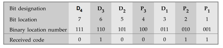
Ex.
1.8.7 Assume that the even parity Hamming code in example (0 1 1 0 0 1 1) is
transmitted and that 0 1 0 0 0 1 1 is received. The receiver does not know what
was transmitted. Determine bit location where error has occurred using received
code.
Sol.
:
Step
1 :
Construct the bit location table.
Step
2 :
Check for parity bits
For
P1 : P1 checks locations 1, 3, 5, and 7.
There
is one 1 in the group.
Parity
checks for even parity is wrong …. →
1 (LSB)
For
P2 : P2 checks locations
2, 3, 6 and 7.
There
are two Is in the group
Parity
check for even parity is correct
….. → 0
For
P3 : P3 checks locations
4, 5, 6 and 7.
There
are one 1 in the group
Parity
check for even parity is wrong
….. → 1
The
resultant word is 1 0 1. This says that the bit in the number 5 location is in
error. It is 0 and should be a 1. Therefore, the correct code is 0 1 1 0 0 1 1,
which agrees with the transmitted code.
Ex.
1.8.8 Deduce the odd parity hamming code for the data : 1010. Introduce an
error in the LSB of the hamming code and deduce the steps to detect the error.
Sol.
:

For
P1 : Bit locations 3, 5 and 7 have two l's
and therefore to have an odd parity, P1 must be 1
For
P2 : Bit locations 3, 6 and 7 have single 1
and therefore to have an odd parity, P2 must be 0
For
P3 : Bit locations 5, 6 and 7 have two Is
and therefore to have an odd parity, P3 must be 1
Hamming
code = 1011001
By
introducing error in LSB we have received
Hamming
code = 1011000
Checking
for error

For
P1 : P1 checks locations
1, 3, 5 and 7. There are two Is in the group
Parity
check for odd parity is wrong … → 1 (LSB)
For
P2 : P2 checks locations
2, 3, 6 and 7. There are single one in the group
Parity
check tor odd parity is correct …
→ 0
For
P3 : P3 checks for
locations 4, 5, 6 and 7. There are three Is in the group
Parity
check for odd parity is correct > 0 (MSB)
The
resultant word = 001. This says that the bit in the number 1 location is in
error.
Ex.
1.8.9 The Hamming code 101101101 is received. Correct it if any errors. There
are four parity hits and odd parity is used.
Sol.
:
Step
1 :
Construct a bit location table

Step
2 :
Check for parity bits
For
P1 : P1 checks locations
1, 3, 5, 7 and 9.
There
are four 1s in the group
Parity
check for odd parity is wrong ….. → 1
(LSB)
For
P2 : P2 checks locations
2, 3, 6 and 7.
There
are three Is in the group
Parity
check for odd parity is correct
….. → 0
For
P3 : P3 checks locations
4, 5, 6 and 7.
There
are three Is in the group
Parity
check for odd parity is correct
…. → 0
For
P4 : P4 checks locations 8
and 9.
There
is one 1 in the group
Parity
check for odd parity is correct
…. → 0
The
resultant word is 0 0 0 1. This says that the bit in the number 1 location is
in error. It is 1 and should be 0. Therefore, the correct code is 1011 0 110 0.
Ex.
1.8.10 Detect and correct error (if any) in the following received even parity
hamming code word 0011110101 0. Also find out the correct message.
Sol.
:
Step
1 :
Find the number of parity bits and information bits We know that, for hamming
code the relationship
2P
> x + P + 1
must
satisfied. The given Hamming code is 11-bit i.e., x + P = 11. Therefore, the
value of P should satisfy following equation :
2P
≥ 12
P
= 4
Thus,
in a given hamming code there are 7 information bits and 4 parity bits.
Step
2 :
Construct a bit location table

Step
3 :
Check for parity bits.
For
P1 : P1 checks location 1,
3, 5, 7, 9 and 11
There
are two l's in the group
A
Parity check for even parity is correct ... 0 (LSB)
For
P2 : P2 checks locations 2,
3, 6, 7, 10 and 11
There
are three l's in the group
A
Parity check for even parity is wrong ….. 1
For
P3 : P3 checks locations
4, 5, 6 and 7
There
are three l's is in the group
A
Parity check for even parity is wrong …..
1
For
P4 : P4 checks locations
8, 9, 10 and 11
There
are two l's in the group
A
Parity check for even parity is correct …. 0 (MSB)
The
resultant word is 0 1 1 0. This says that the bit in the number 6 location is
in error. It is 1 and should be 0. Therefore, the correct message is
00111001010.
b.
Single Error Correction Plus Double Error Detection
•
A hamming code as explained above provides for the detection and correction of
only a single error. With a slight modification, it is possible to construct
hamming code for single-error correction and double-error detection. A one more
parity bit is added in the hamming code to ensure hamming code (including all
parity bits) contains an even number of l's. The added parity bit is not used
in determining the values of the other parity bits. The resulting hamming code
enables single error correction and double error detection.
•
When overall parity bit is correct, there is no single error during the
transmission of the code. If overall parity bit is incorrect, then there is
single error and the bit position of the error can be indicated by binary
number formed after checking the parity bits. Hence, single error correction
can be achieved. If overall parity bit is correct and binary number formed
after checking the parity bits is other than 0-0-0, there are two errors. In
this case, double error detection is achieved. However, no correction is
possible.
Ex.
1.8.11 Given the 8-bit data word 01011011, generate the 13-bit composite word
for the hamming code that corrects single errors and detects double errors.
Sol.
:
Step
1 :
Construct a bit location table.

Step
2: Determine the parity bits for even parity.
For
P1 : D11, D9,
D7 , D5 and D3
=11111 p1 = 1
For
P2 : D11, D10,
D7, D6 and D3 = 1 0 1 0 1 P2 = 1
For
P3 : D12, D7,
D6 and D5 = 0101 P3 = 0
For
P4 : D12, D11 ,
D10 and D9 = 0101 P4 = 0
For
P5 : Since bits 1 through 12 contains odd
number of Is, P5 should be 1 for even parity.
Thus,
the hamming code that corrects single errors and detects double errors for data
word 0101 1011 is 1010101010111.
Ex.
1.8.12 A 12 bit Hamming code word containing 8 bits of data and 4 parity bits
is read from memory. What was the original 8 bit data word that was written
into memory if the 12 bit word read out is as i) 101110010100 and 2)
111111110100
Sol.
:
Out of the 12-bits in the Hamming code, 4 bits located in positions 1, 2, 4, 8
from left are parity bits. The remaining 8 bits are data bits. So the original
8-bit word is made of bits 3, 5, 6, 7, 9, 10, 11 and 12 from left. The data
words are as shown below.

Examples
for Practice
Ex.
1.8.13 : Generate the even parity Hamming codes for following binary data.
a)
110 1 b) 1 0 0 1
[Ans.:
a) 1 1 0 0 1 1 0 b) 1 0 0 1 1 0 0]
Ex.
1.8.14 : A seven bit Hamming code is received aslllllOl. What is the correct
code ?
[Ans.: 1 1 1 1 1 1 1]
Review Questions
1. Write a note on error detecting and correcting codes.
2. Explain the use of parity bit.
3. Explain the hamming code with the help of example.
4. How is it possible to use hamming code for single error
correction and double-error detection ?
5. Given that a frame with bit sequence 1101011011 is
transmitted, it has been received as 1101011010. Determine the method of
detecting the error using any one error detecting code.
AU : Dec.-14, Marks 8
6. Explain Hamming code with an example. State its advantages
over parity codes.
AU : Dec.-14, Marks 8
7. Explain in detail the usage of Hamming codes for error
detection and error correction with an example considering the data bits as
0101.
Digital Logic Circuits: Unit I: (a) Number Systems : Tag: : Number Systems - Error Detection and Correction Codes
Related Topics
Related Subjects

Digital Logic Circuits
EE3302 3rd Semester EEE Dept | 2021 Regulation | 3rd Semester EEE Dept 2021 Regulation