Electric Circuit Analysis: Unit III: Transient Response Analysis
Exercise
Electric Circuit Analysis | Transient Response Analysis
Electric Circuit Analysis: Unit III: Transient Response Analysis : Exercise
EXERCISE
1.
A series RL circuit with R = 10Ω and L = 0.2H has a constant voltage V = 50V
applied at t = 0. Find the resulting current using the Laplace transform
method.
[Ans:
I = 5 - 5e-50t Al
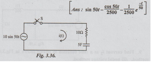
2.
For the circuit shown in fig.3.36, determine the current when the switch is
closed at t = 0. Assume zero charge on the capacitor initially.
3.
A series RLC circuit with R = 52 and L = 0.1 H and C = 500 μF has a constant
voltage V = 10V applied at t = 0. Find the resulting current.
[Ans:
i = 0.72 e-25t sin 139t A]
4.
For the circuit shown in fig.3.37, the switch is closed at t = 0. Find i2 (t)
for t> 0. Assume zero initial energy. Use Laplace transform technique.
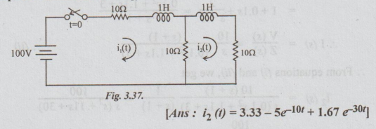
[Ans: i2 (1) = 3.33-5e-10t +
1.67 e-30t]
5.
A voltage of 100V DC is applied to a series circuit consisting of R and C = 50
μF. If the voltage across C is observed to be 50V at t = 1 sec, determine the
value of R in the circuit. Sketch the waveform of voltage across C.
[Ans:
R= 28.854 KΩ]
6.
A series RLC circuit with R = 59, L = 0.1H and C = 500 μF has a sinusoidal
voltage source V = 100 sin (250t+) volts. Find the resulting current if the
switch is closed when = 0°.
[Ans:
i = e-25t (5.42 cos 139t + 1.89 sin 1391) + 5.65 sin (250t - 73.6°)A]
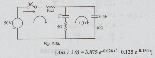
7.
In the network shown in fig.3.38. below, the switch is closed at t = 0 and
there is no initial charge on either of the capacitors. Find the resulting
current i (t) using Laplace transformation.
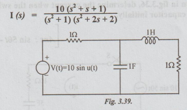
8.
If the capacitors are uncharged and the inductor current is zero at t = 0 in
the network shown in Fig.3.39 below, show that the transform of the generation
current is
9.
Find current i, as a time function in circuit shown in Fig.3.40 using (i) loop
current method, (ii) nodal voltage method.
Assume
all initial conditions to be zero.

[Ans
: 3 (1 – e-t - e-2t + e-3t) amp.]
[Note: The student may proceed for solving the
problem after drawing the circuit diagram in s- domain.]
Electric Circuit Analysis: Unit III: Transient Response Analysis : Tag: : Electric Circuit Analysis | Transient Response Analysis - Exercise
Related Topics
Related Subjects

Electric Circuit Analysis
EE3251 2nd Semester 2021 Regulation | 2nd Semester EEE Dept 2021 Regulation