Electric Circuit Analysis: Unit I: b. Basic circuits analysis
Exercise problems: Solving the Electrical Network
Loop current method, Node Voltage Method
Electric Circuit Analysis: Unit I: Basic circuits analysis : Exercise problems
EXERCISE PROBLEMS
LOOP CURRENT METHOD
1. In the circuit of figure, find
the current I by the mesh method.
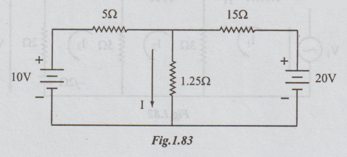
[Ans:
2.5 A]
2. Obtain the currents in all the
branches of the network in figure by mesh method.
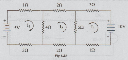
[Ans:
I1 = 0.44 A, I2 = 0.37 A, I3 = 1.32 A]
3. In the network shown determine
the direction and magnitude of current flow in the milli ammeter A having a
resistance of 10Ω.
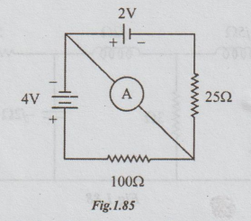
[Ans:
26.7 mA]
4. A voltage source V3
causes the mesh current I1 to be zero. Find the value of V3.
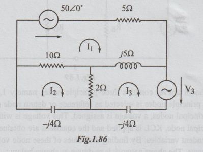
[Ans:
16.8 <133.2° volts]
5. In a circuit shown below, determine the power in the impedance 2 + j5 Ω cor.nected between A and B. Use loop current method to find the current and verify the answer by simplification of series parallel combination.
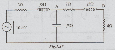
[Ans: 2.69 watts]
6. In the network of the figure, find V2 such that the V2 source current will be zero.
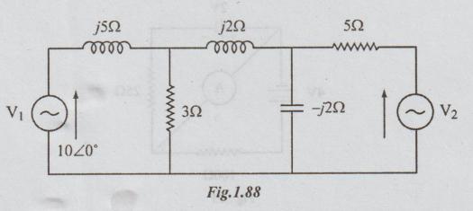
[Ans:
V2=4 / 180°V]
Node Voltage Method of Solving the Electrical Network
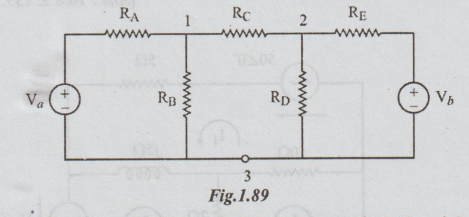
The
network shown above, contains three principle nodes namely 1, 2 and 3. In node
voltage method, one of the principle nodes is selected as reference or datum
node (or zero potential node). At each of the other principal nodes, a voltage
is assigned. This voltage is with reference to the reference node. At each
principal node, KCL is applied and the equations are obtained. In this method,
the node voltages are independent variables. By finding the values of these
node voltages, we can calculate the various branch currents. The above network
is re-drawn as shown below:
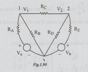
Node
3 is taken as reference.
V1
and V2 are the node voltages at nodes 1 and 2 respectively.
At
node 1, applying KCL, we get
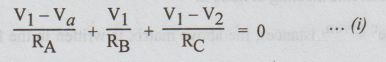
and at node 2 application of KCL yields
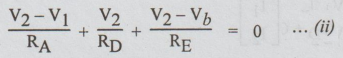
Rearranging
the equations (1) & (2), we get
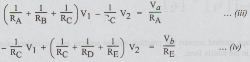
Putting
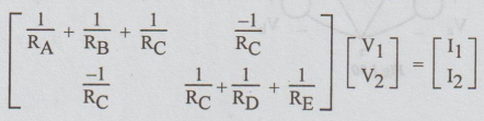
equations (3) & (4) in the matrix form, we get
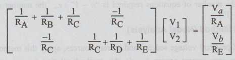
1-1
element contains sum of reciprocals of all resistances connected to 1. 2-2
element contains sum of reciprocals of all resistances connected to node 2. 1-2
and 2 - 1 elements are each equal to the negative of the sum of the reciprocals
of the resistances of all branches joining nodes 1 and 2. (In the present case
there is only one resistance between 1 and 2 i.e., RC). Voltage
matrix contains the independent variables V1 and V2.
Current
matrix contains Va/RAand Vb/RE. These
are called driving currents. The driving currents are positive if they flow
towards the principal node. If the driving current flows away from principal
node, it is taken as negative.
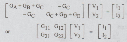
The
above matrix can be written as below in the general form,
I1
= algebraic sum of all driving currents meeting at node 1.
12
=algebraic sum of all driving currents meeting at node 2.
If
the conductance's are given, instead of resistances, the above matrix is
written in the following form,
[Note:
1.
In applying node voltage method convert the practical voltage sources into
equivalent current sources before putting in the matrix form.
2.
This method can be applied for both AC and DC circuits.
3.
If there are "n" nodes, then the number of equations required is
"n - 1" i.e., the number of unknown node voltages is "n -
1"]
To solve DC network by Nodal Method
(Nodal Analysis)
[Note:
If the circuit consists of practical voltage sources and current sources, apply
this method after converting the voltage source into current source i.e., in
this method solution is easier or convenient if all the sources are current sources.
Then, by inspection, we can obtain the nodal equations in the matrix form and
proceed for solving the network. Also the student is to note whether the given
passive element is resistance [ohms] or conductance [mhos or siemen]. ]
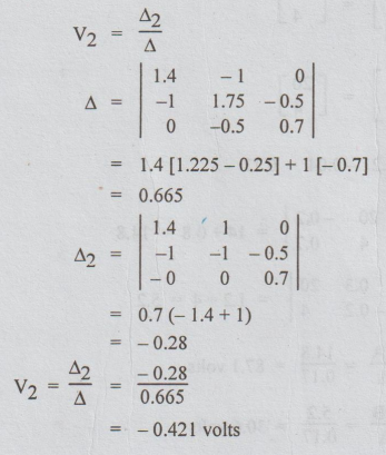
Example
9 Frame the nodal equations of the network of figure and hence find the
difference of potential between nodes 2 and 4.
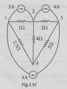
Solution:
Let the node 4 be the reference i.e., zero potential node. Let V1, V2
and V3 be the node voltages at the nodes 1, 2 and 3 respectively. By
inspection,
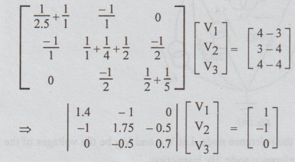
It
is required to find the difference of potential between nodes 2 and 4. i.e., V2-V4
= V2-0= V2. So, it is enough if we know the value of V2.
Example
10 Compute the voltage at nodes A and B in the circuit of figure.1.92
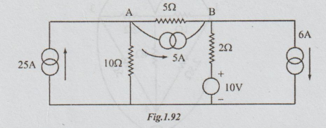
Solution:
First
converting the voltage source into its equivalent current source and re-drawing
the circuit the following figure is obtained.
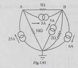
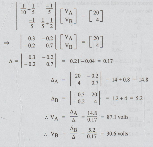
There
are two nodes A and B other than the reference node. Let VA and VB
be the voltages of the nodes A and B respectively with respect to reference
node. By inspection,
Example
11 Use nodal voltage method and hence find the power dissipated in the 10 ohms
resistor on the circuit shown in figure.
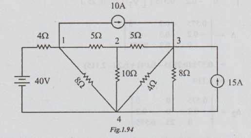
Solution:
Taking
the node 4 as reference, and converting the voltage source into current source,
the above network is re-drawn as below:
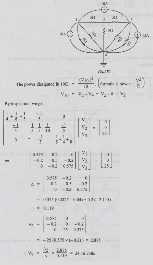
Therefore,
the potential difference across 10 ohms = 'V10
=
24.16 volts
Power
dissipated in 10Ω =(24.16)2 /10
=58.4
Watts
Example
12 Find the currents I1, I2 and I3 and the
voltages Va and Vb in the network of figure by using
nodal analysis.
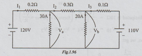
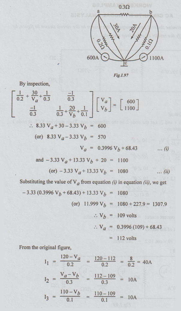
Solution:
Converting the voltage source into current source, the following circuit is
obtained.
Electric Circuit Analysis: Unit I: b. Basic circuits analysis : Tag: : Loop current method, Node Voltage Method - Exercise problems: Solving the Electrical Network
Related Topics
Related Subjects

Electric Circuit Analysis
EE3251 2nd Semester 2021 Regulation | 2nd Semester EEE Dept 2021 Regulation