Electrical Machines II: UNIT II: Synchronous Motor
Expression for Back E.M.F. or Induced E.M.F. per phase in Synchronous Motor (Ebph)
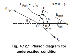
So once Ebpb is calculated, load angle δ can be determined by using sine rule.
Expression for Back E.M.F. or Induced E.M.F. per phase in
Synchronous Motor (Ebph)
case
i] Under excitation, Ebph < Vph.
ZS
= Ra + j XS = | ZS| ∠ ϕ Ω
θ
= tan-1 (XS / Ra )
ERph^
Iaph = θ Ia lags ER always by angle θ
Vph
= Phase voltage applied
Ebph
= Back e.m.f. induced per phase
ERph
= Ia × Zs V ...
Per phase
Let
p.f. be cos ϕ
, lagging as under excited,
Vph
^ Iaph = ϕ
Phasor
diagram is shown in the Fig. 4.12.1. Applying cosine rule to ∆ OAB,
So
once Ebpb is calculated, load angle 8 can be determined by using sine rule.
Case
ii]
Over excitation, Ebph > Vpb Ebph
p.f.
is leading in nature.
ERph
^ Iaph = θ
Vph
^ Iaph = ϕ
The
phasor diagram is shown in the Fig. 4.12.2.
Applying
cosine rule to ∆ OAB,
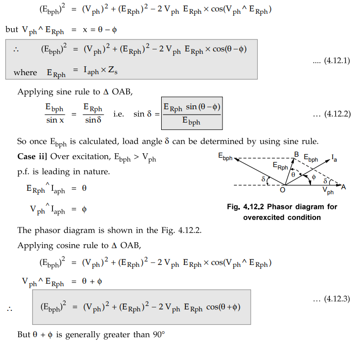
But
θ + ϕ is generally greater
than 90°
cos
(θ + ϕ) becomes negative,
hence for leading p.f., Ebph > Vph.
Applying
sine rule to ∆ OAB,
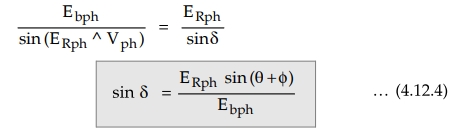
Hence
load angle δ, can be calculated once Ebph is known.
Case
iii]
Critical excitation
In
this case Ebph ≅ Vph, but
p.f. of synchronous motor is unity.
cos
ϕ = 1
ϕ
= 0o
i.e.
Vph and Iaph are in phase.
and
ERph Λ Iaph = θ
Phasor
diagram is shown in the Fig.4.12.3.
Applying
cosine rule to ∆ OAB,
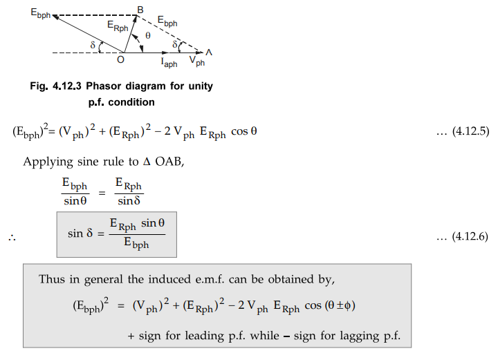
Thus
in general the induced e.m.f. can be obtained by,
(Ebph)2
= (Vph)2 + (ERph)2 - 2 Vph
ERph cos (θ ± ϕ)
+
sign for leading p.f. while - sign for lagging p.f.
Example
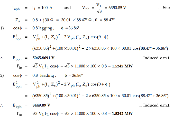
4.12.1 A 3 phase 11000 V, star connected synchronous motor
takes a load of 100 A. The effective synchronous reactance and resistance per
phase are 30 Ω and 0.8 Ω respectively. Find the power supplied to the motor and
the induced EMF for
1)
0.8 p.f. lag 2) 0.8 p.f. lead.
Solution
:
VL
= 11000 V, IL = 100 A, Ra = 0.8 Ω, Xs =
30 Ω
Example
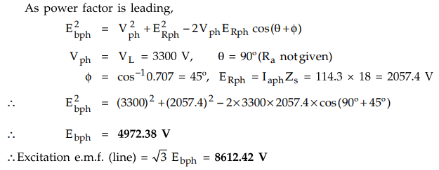
4.12.2 A 3300 V, delta connected motor has a synchronous
reactance per phase of 18 Ω. It operates at a leading power factor of 0.707
when drawing 800 kW from the mains. Calculate its excitation e.m.f.
AU : May-2016, Marks 8
Solution
: VL
= 3300 V, delta, cos ϕ = 0.707, XS = 18 Ω , Pin
= 800kW
Pin
= √3 VL IL cos ϕ
i.e. IL = 800 × 103 / √3
× 3300 × 0.707 = 197.97 A
Iaph
= IL / √3 = 114.3 A … delta
As
power factor is leading,
Example
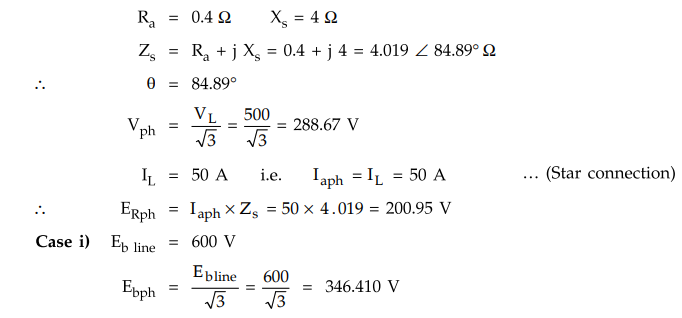
4.12.3 A 3 phase, 500 V, synchronous motor draws a
current of 50 A from the supply while driving a certain load. The stator is
star connected with armature resistance of 0.4 Ω per phase and a synchronous
reactance of 4 Ω per phase. Find the power factor at which motor would operate
when the field current is adjusted to give the line values of generated e.m.f.
as i) 600 V and ii) 380 V
Solution
:
VL = 500 V star connection
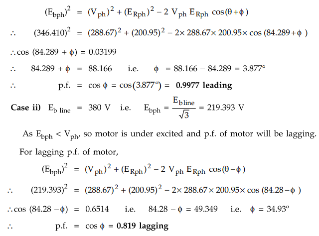
Ebph
> Vph , hence motor is over excited and the power factor will be
leading. For leading power factor,
Examples
for Practice
Example
4.12.4 A 400 V, 3 phase, star connected synchronous
motor has an armature resistance of 0.2 Ω per phase and synchronous reactance
of 2 Ω per phase. While driving a certain load, it takes 25 A from the supply.
Calculate the back e.m.f. induced in the motor if it is working with i) 0.8
lagging ii) 0.9 leading and iii) Unity power factor conditions.
[Ans.:
i) 200.505 V ii) 252.562 V iii) 231.38 V]
Example
4.12.5 A three phase, 6600 V, star connected
synchronous motor delivers 500 kW power to the full load. Its full load
efficiency is 83 %. Its armature resistance is 0.3 Ω per phase and synchronous
reactance is 3.2 Ω per phase. It is working with 0.8 leading power factor on
full load. Calculate : i) generated e.m.f. on full load, ii) the load angle.
[Ans.:
i) 3925.31 V ii) δ = 2.63°]
Example
4.12.6 A 2300 V, 3-phase, star-connected synchronous
motor has a resistance of 0.2 Ω per phase and a synchronous reactance of 2.2 Ω/phase.
The motor is operating at (0.5 p.f.) leading with a line current of 200 A.
Determine the value of the generated e.m.f. per phase.
[Ans.:
1708.012 V]
Review Questions
1. Derive the expression for induced e.m.f. per phase in a
synchronous motor.
2. Draw and explain the phasor diagram of a cylindrical rotor
synchronous motor operating at different power factors.
Electrical Machines II: UNIT II: Synchronous Motor : Tag: Engineering Electrical Machines - II : - Expression for Back E.M.F. or Induced E.M.F. per phase in Synchronous Motor (Ebph)
Related Topics
Related Subjects

Electrical Machines II
EE3405 Machine 2 EM 2 4th Semester EEE Dept | 2021 Regulation | 4th Semester EEE Dept 2021 Regulation