Linear Integrated Circuits: Unit III: Applications of Op-amp
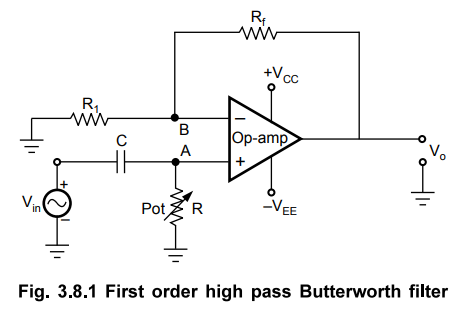
First Order High Pass Butterworth Filter using Op-amp
Operational amplifier
Hence, the high pass filter circuit can be obtained by interchanging frequency determining resistances and capacitors in low pass filter circuit.
First Order High Pass Butterworth Filter
As
mentioned earlier, a high pass filter is a circuit that attenuates all the
signals below a specified cut off frequency denoted as fL. Thus, a high pass
filter performs the opposite function to that of low pass filter. Hence, the
high pass filter circuit can be obtained by interchanging frequency determining
resistances and capacitors in low pass filter circuit.
The
first order high pass filter can be obtained by interchanging the elements R
and C in a first order low pass filter circuit. The Fig. 3.8.1 shows the first
order high pass Butterworth filter.
It
can be observed that as compared to first order low pass filter (Fig. 3.4.1),
the positions of R and C are changed in the high pass circuit shown in Fig.
3.8.1.
The
frequency at which the gain is 0.707 times the gain of filter in pass band is
called low cut-off frequency and denoted as fL. So, all the
frequencies greater than fL are allowed to pass but the maximum
frequency which is allowed to pass is determined by the closed loop bandwidth
of the op-amp used.
1. Analysis of the Filter Circuit
The
impendance of the capacitor is – jXC = -j (1 / 2π f C) where f is
the input i.e. operating frequency.
By
the voltage divider rule, the potential of the non inverting terminal of the
op-amp is,
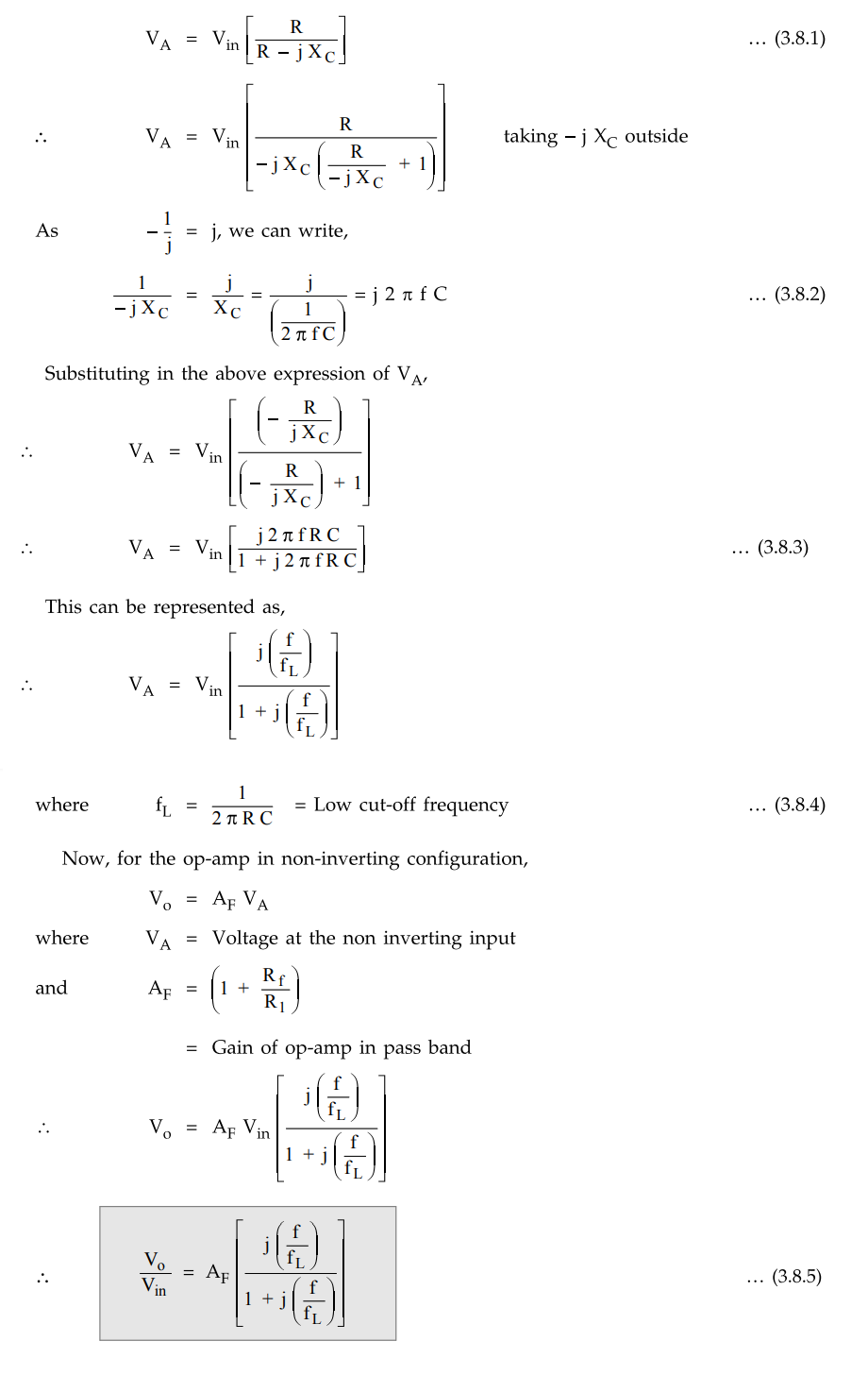
This
is the required expression for the transfer function of the filter.
For
the frequency response, we require the magnitude of the transfer function which
is given by,
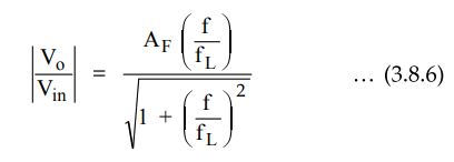
The
equation (3.8.6) describes the behaviour of the high pass filter.
1)
At low frequencies, i.e. f < fL
|Vo
/ Vin| < AF
2)
At f = fL,
|Vo
/ Vin| = 0.707 AF i.e. 3 dB down from the level of AF
3)
At f > fL, i.e. high frequencies, 1 can be neglected as compared
to denominator.
|Vo
/ Vin| ≅ AF i.e.
constant
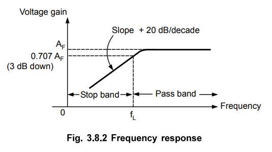
Thus,
the circuit acts as high pass filter with a passband gain as AF. For the
frequencies, f < fL, the gain increases till f = fL at
a rate of +20 dB/decade. Hence, the slope of the frequency response in stop
band is + 20 dB/decade for first order high pass filter.
The
frequency response is shown in the Fig. 3.8.2.
Note
As high pass filter is basically a low pass filter circuit with positions of
R and C interchanged, the design steps and the frequency scaling method
discussed earlier for low pass filter is equally applicable to the first order
high pass butterworth filter.
Example
3.8.1 Design a high pass filter with a cut-off
frequency of 10 kHz with a passband gain of 1.5.
Solution
:
Step
1 :
The lower cut-off frequency is 10 kHz. i.e fL = 10 kHz
Step
2 :
Choose C less than 1 µF. hence C = 0.02 µF
Step
3 :
Calculate R
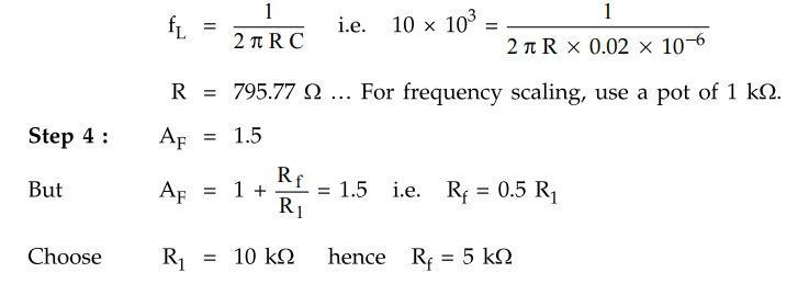
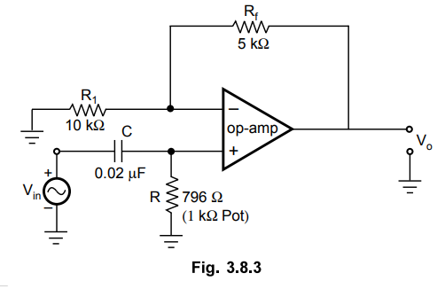
The
complete circuit is shown in the Fig. 3.8.3.
Review Question
1. Draw and explain
the operation of first order high pass butterworth filter.
Linear Integrated Circuits: Unit III: Applications of Op-amp : Tag: : Operational amplifier - First Order High Pass Butterworth Filter using Op-amp
Related Topics
Related Subjects

Linear Integrated Circuits
EE3402 Lic Operational Amplifiers 4th Semester EEE Dept | 2021 Regulation | 4th Semester EEE Dept 2021 Regulation