Linear Integrated Circuits: Unit III: Applications of Op-amp
First Order Low Pass Butterworth Filter using Op-amp
Operational amplifier
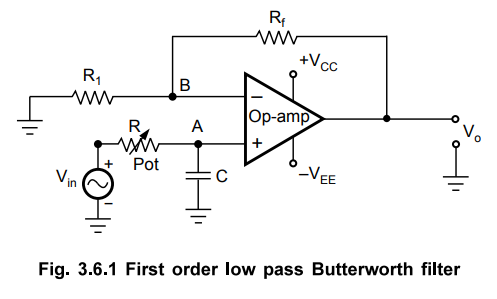
The first order low pass butterworth filter is realised by R-C circuit used alongwith an op-amp, used in the noninverting configuration. The circuit diagram is shown in Fig. 3.6.1.
First Order Low Pass Butterworth Filter
The
first order low pass butterworth filter is realised by R-C circuit used
alongwith an op-amp, used in the noninverting configuration. The circuit
diagram is shown in Fig. 3.6.1.
This
also called one pole low pass Butterworth filter.
The
resistances Rf and Rf decide the gain of the filter in
the pass band.
1. Analysis of the Filter Circuit
The
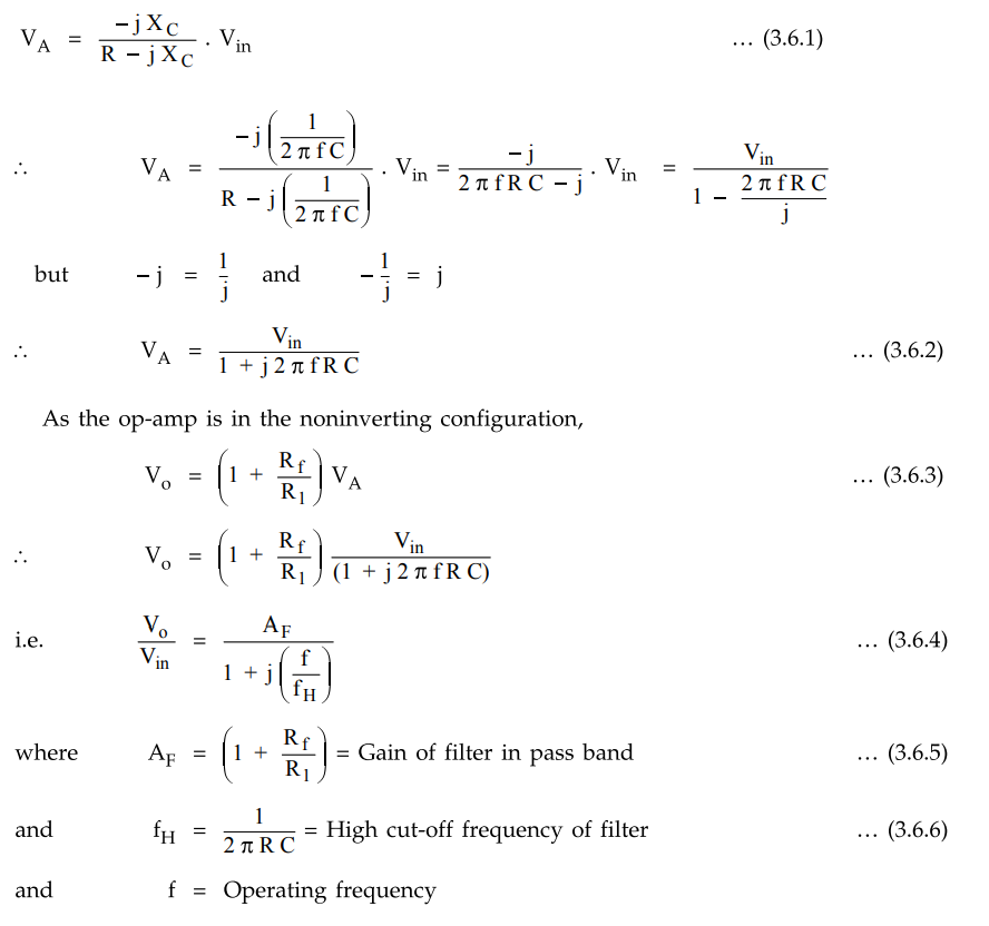
impedance of the capacitor C is - jXC where XC is the
capacitive reactance given by XC = 1 / 2π f C.
By
the potential divider rule, the voltage at the noninverting input terminal A
which is the voltage across capacitor C is given by,
The
Vo / Vin is the transfer function of the filter and can
be expressed in the polar form as
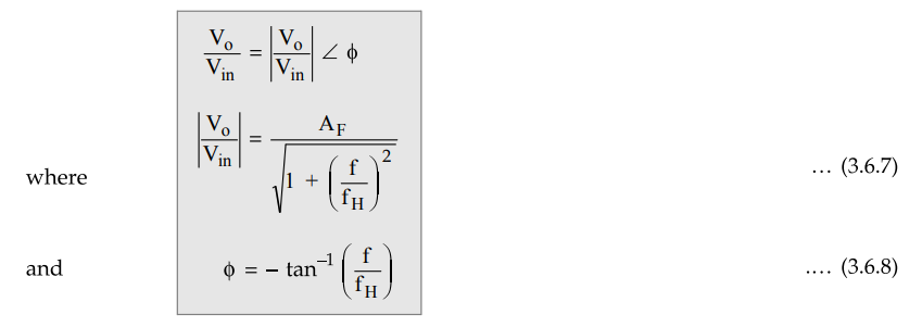
The
phase angle ϕ is in degrees.
The equation (3.6.7) describes the behaviour of the low pass filter.
1. At very low
frequencies, f < fH
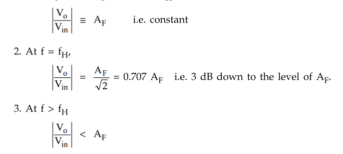
Thus,
for the range of frequencies, 0 < f < fH, the gain is almost
constant equal to fH which is high cut off ( frequency. At f = fH,
gain reduces to 0.707 AF i.e. 3 dB down from AF. And as
the frequency increases than fH, the gain decreases at a rate of 20 dB/decade. The rate 20 dB/decade
means decrease of 20 dB in gain per 10 times change in frequency. The same rate
can be expressed as 6 dB/octave i.e. decrease of 6 dB per two times change in
the frequency. The frequency fH is called cut off frequency, break
frequency, - 3 dB frequency or corner frequency. The frequency response is
shown in the Fig. 3.6.2.
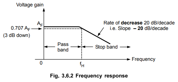
Key
Point The rate of decrease in gain is 20 dB/decade
i.e. the decrease can be indicated by a negative slope in the frequency
response, as - 20 dB/decade.
2. Design Steps
The
design steps for the first order low pass Butterworth filter are
1)
Choose the cut off frequency, fH.
2)
Choose the capacitance C usually betwen 0.001 and 1 µF. Generally, it is selected
as 1 µF or less than that. For better performance, mylar or tantalum capacitors
are selected.
3)
Now, for the RC circuit,
fH
= 1 / 2 π R C ... Refer equation (3.6.6)
Hence,
as fH and C are known, calculate the value of R.
4)
The resistances Rf and R1 can be selected depending on
the required gain in the pass band.
AF
= 1 + Rf / R1
3. Frequency Scaling
Once
the filter is designed, sometimes, it is necessary to change the value of
cut-off frequency fH. The method used to change the original cut-off frequency
fH to a new cut-off frequency fH1 is called as frequency scaling.
To
achieve such a frequency scaling, the standard value capacitor C is selected
first. The required cut-off frequency can be achieved by calculating
corresponding value of resistance R. But to achieve frequency scaling a
potentiometer is used as shown in Fig. 3.6.1. Thus, the resistance R is
generally a potentiometer with which required cut-off frequency fH can
be adjusted and changed later on if required.
Example
3.6.1 Design a first order low pass filter for a high
cut-off frequency of 1 kHz and pass band gain of 2.
Solution
:
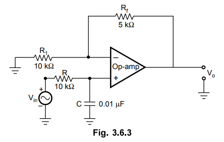
The
designed circuit is shown in the Fig. 3.6.3.
Review Questions
1. Draw the circuit of
a first order active low pass filter and derive its frequency response and plot
the same.
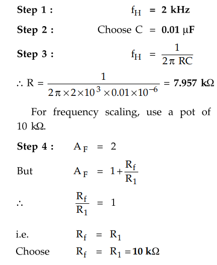
2. Design a first
order low pass filter for cut-off frequency of 2 kHz and pass band gain of 2.
May-13, Marks 8
[Ans.: Refer example 3.4.2 and Verify Rf = R1 = 10 kΩ, C = 0.001 µF, R = 79.57 kΩ ]
Linear Integrated Circuits: Unit III: Applications of Op-amp : Tag: : Operational amplifier - First Order Low Pass Butterworth Filter using Op-amp
Related Topics
Related Subjects

Linear Integrated Circuits
EE3402 Lic Operational Amplifiers 4th Semester EEE Dept | 2021 Regulation | 4th Semester EEE Dept 2021 Regulation