Electrical Machines: Unit I: a. Magnetic Circuits and Electromagnetism
Force on a Current Carrying Conductor in a Magnetic Field
We have already mentioned that magnetic effects of electric current are very useful in analysing various practical applications like generators, motors etc. One of such important effects is force experienced by a current carrying conductor in a magnetic field.
Force on
a Current Carrying Conductor in a Magnetic Field
AU : Dec.-16
•
We have already mentioned that magnetic effects of electric current are very
useful in analysing various practical applications like generators, motors etc.
One of such important effects is force experienced by a current carrying
conductor in a magnetic field.
•
Let a straight conductor, carrying a current is placed in a magnetic field as
shown in the Fig. 1.25.1(a).
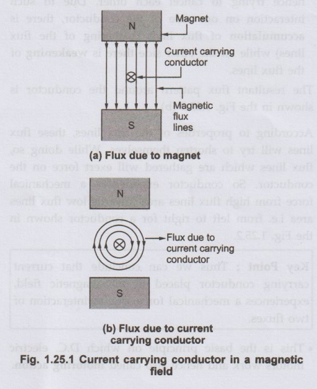
•
The magnetic field in which it is placed has a flux pattern as shown in the
Fig. 1.25.1 (a).
•
Now current carrying conductor also produces its own magnetic field around it.
Assuming current direction away from observer i.e. into the paper, the
direction of its flux can be determined by right hand thumb rule. This is
clockwise as shown in the Fig. 1.25.1 (b). [For simplicity, flux only due to
current carrying conductor is shown in the Fig. 1.25.1 (b)].
• Now there is presence of two magnetic fields namely due to permanent magnet and due to current carrying conductor. These two fluxes interact with each other. Such interaction is shown in the Fig. 1.25.2 (a).
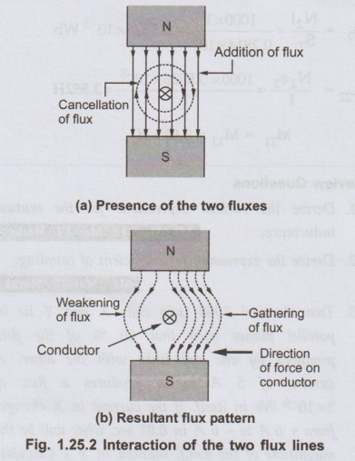
• This interaction as seen is in such a way that on one side of the conductor the two lines help each other, while on other side the two try to cancel each other. This means on left hand side of the conductor shown in the Fig. 1.25.2 the two fluxes are in the same direction and hence assisting each other. As against this, on the right hand side of the conductor the two fluxes are in opposite direction hence trying to cancel each other. Due to such interaction on one side of the conductor, there is accumulation of flux lines (gathering of the flux lines) while on the other side there is weakening of the flux lines. The resultant flux pattern around the conductor is shown in the Fig. 1.25.2 (b).
According to properties of the flux lines, these flux lines will try to shorten themselves. While doing so, flux lines which are gathered will exert force on the conductor. So conductor experiences a mechanical force from high flux lines area towards low flux lines area i.e. from left to right for a conductor shown in the Fig. 1.25.2.
Key Point :
Thus we can conclude that current carrying conductor placed in the magnetic field,
experiences a mechanical force, due to interaction of two fluxes.
•
This is the basic principle on which D.C. electric motors work and hence also
called motoring action.
1. Fleming's Left Hand Rule
•
The direction of the force experienced by the current carrying conductor placed
in magnetic field can be determined by a rule called 'Fleming's Left Hand
Rule'. The rule states that, 'Outstretch the three fingers of the left hand
namely the first finger, middle finger and thumb such that they are mutually
perpendicular to each other. Now point the first finger in the direction of
magnetic field and the middle finger in the direction of the current then the
thumb gives the direction of the force experienced by the conductor'.
•
The rule is explained in the diagrammatic form in the Fig. 1.25.3.

Apply
the rule to crosscheck the direction of force experienced by a single
conductor, placed in the magnetic field, shown in the Fig. 1.25.4 (a), (b), (c)
and (d).

2. Magnitude of Force Experienced by the Conductor
• The magnitude of the force experienced by the conductor depends on the
following factors, 1) Flux density (B) of the magnetic
field in which the conductor is placed measured in Wb/m2 i.e. Tesla.
2)
Magnitude of the current I passing through the conductor in Amperes.
3)
Active length 'l' of the conductor in metres.
The
active length of the conductor is that part of the
conductor which is actually under the influence of magnetic field.
If
the conductor is at right angles to the magnetic field as shown in Fig. 1.25.5
(a) then force F is given by,
F
= B I l Newtons
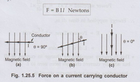
But
if the conductor is not exactly at right angles, but inclined at angle θ
degrees with respect to axis of magnetic field as shown in the Fig. 1.25.5 (b)
then force F is given by,
F = B I lsin θ Newtons
As
shown in the Fig. 1.25.5 (c), if conductor is kept along the lines of magnetic
field then 0 = 0° and as sin θ = 0o, the force experienced by the
conductor is also zero.
Key Point :
The direction of such force can be reversed either by changing the direction of
current or by changing the direction of the flux lines in which it is kept. If
both are reversed, the direction of force remains same.
Ex. 1.25.1
Calculate the force experienced by the conductor of 20 cm long, carrying 50
amperes, placed at right angles to the lines of force of flux density 10x10-3
Wb/m2.
Sol. :
The force experienced is given by,
F = B I l sin θ where sin (θ) = 1 as θ = 90
degrees
B
= Flux density = 10x10-3 Wb/m2
1
= Active length = 20 cm = 0.2 m
I
= Current = 50 A
F
= 10x10-3 × 50 × 02 = 0.1 N
Review Questions
1. Derive the
expression for the force experienced by the current carrying conductor placed
in a magnetic field. AU : Dec.-16, Marks 8
2. Explain Fleming's
left hand rule.
Electrical Machines: Unit I: a. Magnetic Circuits and Electromagnetism : Tag: : - Force on a Current Carrying Conductor in a Magnetic Field
Related Topics
Related Subjects

Electrical Machines I
EE3303 EM 1 3rd Semester EEE Dept | 2021 Regulation | 3rd Semester EEE Dept 2021 Regulation