Linear Integrated Circuits: Unit IV: Special ICs
Four Quadrant Variable Transconductance Multiplier Circuit
Operating working principle
The heart of the four quadrant variable transconductance multiplier circuit is the linearized transconductance multiplier and the differential V-I converter. Let us study these two circuits in brief.
Four Quadrant Variable Transconductance Multiplier Circuit
AU
: May-05, 18, Dec.-12, 14
The
heart of the four quadrant variable transconductance multiplier circuit is the
linearized transconductance multiplier and the differential V-I converter. Let
us study these two circuits in brief.
1. Linearized Transconductance Multiplier
This
circuit consists of a differential pair of transistors Q3 - Q4
to provide a variable transconductance and the transistors Q1 - Q2
used as diode with base-collector shorted. This is shown in the Fig. 4.9.1.
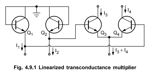
Applying
KVL to the pair Q1 - Q2 and Q3 - Q4
VBE1
+ VBE4 = VBE2 + VBE3
i.e.
VBE3 - VBE4 = VBEI - VBE2 …. (4.9.1)
For
the two matched transistors, the change in VBE is proportional to the log ratio
of their currents. Hence,

Key
Point : Thus current multiplies the differential current
(I1- I2) by total emitter current (I3+ I4)
To
get (I1- I2) and (I3- I4) from the
input voltages V1 and V2, two V-I converters are necessary and to convert (I3-
I4) to the output voltage Vo, one I-V converter is must.
2. Differential V-I Converter
To convert input voltages to get differential current, V-I converter circuit is used as shown in the Fig. 4.9.2.
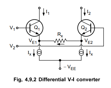
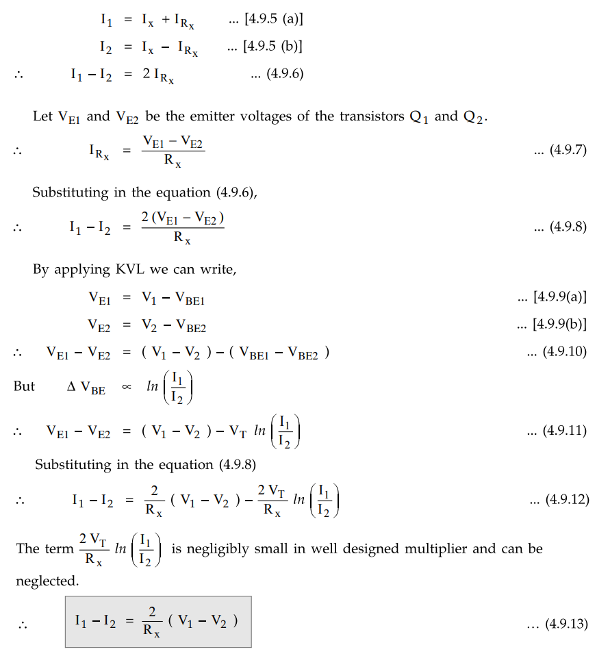
Ignoring the two base currents and applying
KCL we get,
Key
Point Thus circuit performs V-I conversion.
The
linearized transconductance multiplier operates only over two quadrants. Hence
using little modifications and using differential V-I converter, the four
quadrant variable transconductance multiplier circuit is obtained in practice.
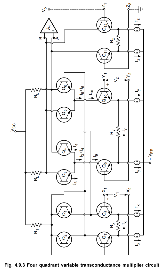
3. Four Quadrant Multiplier Circuit
The
Fig. 4.9.3 shows the complete four quadrant variable transconductance
multiplier circuit. It uses two linearized transconductance pairs with bases
driven in antiphase. The emitters are driven by V-I converters.
We
have derived earlier that for linearized transconductance multiplier circuit,
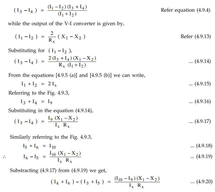
But
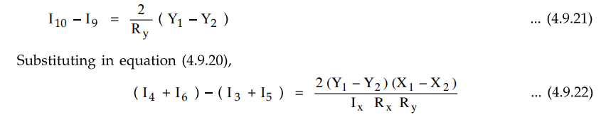
the transistors Q9 and Q10 form another V-I converter for
which we can write, referring to the equation (4.9.13) as,
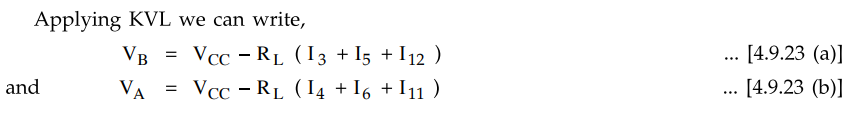
The
op-amp A1 alongwith the third V-I converter of transistors Q11 and Q12, form
the output I-V converter. The V-I converter of Qn and is in the feedback path
of op-amp A1.
Applying
KVL we can write,
But
for an op-amp, the two input terminals are always at same potential i.e. (VA
=VB).

But
as Q11 and Q12 form another V-I converter, referring to
the equation (4.9.13) we can write,
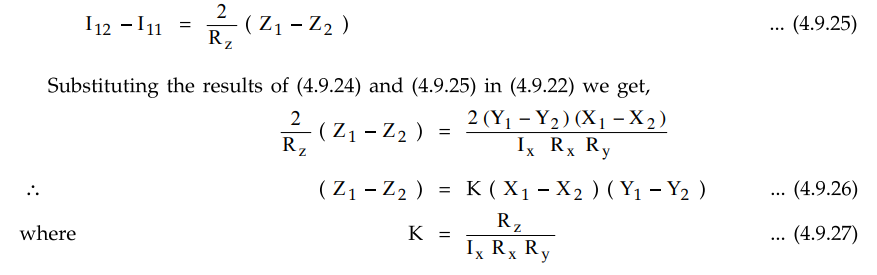
Generally
K is selected as (1 / 10) and thus the equation (4.9.27) shows that the circuit
functions as a four quadrant multiplier circuit.
So
let V1 = X 1 - X2
and V2 = Y1 - Y2
while Vo = Z1- Z2
hence Vo = K V1V2 … (4.9.28)
The
Fig. 4.9.4 shows the four quadrant transfer characteristics of the
transconductance multiplier
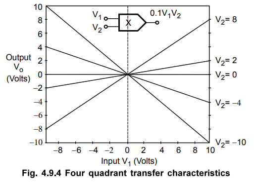
circuit
shown in the Fig. 4.9.4, with value of the constant K as 0.1.
The
logarithmic term neglected in the V-I converter analysis may be the main cause
of error but it is compensated by introducing equal and opposite logarithmic
term by means of third V-I converter of
Q11 - Q12 which is in the feedback path.
For
maximum flexibility, the resistances R1 RL, Rx,
Ry and Rz have been left external to the circuit. This is
used to vary the scale factor K and common mode ranges of the circuit
independently.
This
circuit is commonly used for monolithic IC realization and available in
monolithic form from variety of manufacturers. The two popular examples of four
quadrant multiplier IC are AD 534 by Analog Devices and MPY 100 by Burr-Brown.
Review Question
1. Explain, with
necessary equations, the basic circuits of 'Linearized transconductance
multiplier' and differential V-I converter' Hence explain the 'Four quadrant
variable transconductance multiplier' circuit.
Linear Integrated Circuits: Unit IV: Special ICs : Tag: : Operating working principle - Four Quadrant Variable Transconductance Multiplier Circuit
Related Topics
Related Subjects

Linear Integrated Circuits
EE3402 Lic Operational Amplifiers 4th Semester EEE Dept | 2021 Regulation | 4th Semester EEE Dept 2021 Regulation