Basic Civil & Mechanical Engineering: UNIT IV: g. Internal combustion engines
Four Stroke Cycle Engines
Petrol, Diesel Engine | Cycle of operation, Classification
Four Stroke Cycle Engine: In the four stroke engine, there is one power stroke in every four strokes or during two revolutions of the crank. The four stroke engines are further classified as Four Stroke Petrol Engine and Four Stroke Diesel Engine according to the type of fuel used in the engine.
FOUR STROKE CYCLE
ENGINES
Cycle of Operation:
There are distinctly four strokes, viz., Suction Stroke, Compression Stroke,
Expansion Stroke and Exhaust Stroke for different Operations in a Cycle. Each
stroke is identified as per the function.
Classification of 1.C. Engines:
The internal combustion engines are classified as Four Stroke and Two Stroke
Engines.
Four Stroke Cycle Engine:
In the four stroke engine, there is one power stroke in every four strokes or
during two revolutions of the crank. The four stroke engines are further
classified as Four Stroke Petrol Engine and Four Stroke Diesel Engine according
to the type of fuel used in the engine.
1. FOUR STROKE PETROL ENGINE
Petrol
Engine is also known as Spark Ignition (S.I.) Engine. Four Stroke Petrol Engine
requires four strokes of the piston to complete one cycle of operation in the
engine cylinder.
See
Fig. 2. It consists of a cylinder. Its one end is fitted with a cover and the
other end left open. The cover is provided with inlet and exhaust apertures.
These apertures are opened and closed by inlet and exhaust valves. A spark plug
initiates the ignition of the fuel. The piston reciprocates inside the
cylinder. The connecting rod and crank convert the reciprocating motion of the
piston into rotary motion.
Power Cycle of Petrol Engine – Otto
Cycle
The
petrol engine works on the principle of Otto Cycle, also known as Constant
Volume Cycle. Fig. 3 shows the Pressure Velocity Diagram of Theoretical Otto
Cycle.
1. Suction Stroke: Fig. 2(a)
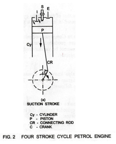
During
suction stroke, the Inlet valve (I) opens and air and fuel (petrol) mixture
(charge) is sucked into the cylinder. The piston moves downward from Top Dead
Center (TDC) till it reaches Bottom Dead Center (BDC). During suction stroke
the Exhaust value (E) is closed.
See
Fig. 3. Suction stroke is theoretically represented by the horizontal line 1-2
in the PV Diagram. The drawal of air-fuel mixture is taking place at
atmospheric pressure.
2. Compression Stroke: Fig. 2(b)
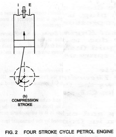
During this stroke, both the inlet and exhaust
valves are closed. The air-fuel mixture is compressed as the piston moves
upwards from BDC to TDC. The compression ratio in petrol engines varies from 7
to 10. As a result of compression, pressure and temperature of the charge are
increased to 15-20 bar and 400°C respectively.
See
Fig. 3. The process of compression is theoretically represented by the curve
2-3 in the PV Diagram.
Shortly
before the piston reaches TDC, the charge is ignited by means of a Spark Plug.
It suddenly increases the pressure and temperature of the products of
combustion, but the volume remains constant.
During
the burning process, the chemical energy of the fuel is converted into heat
energy, producing a temperature rise of about 2000° C.
See
Fig. 3. This constant volume combustion process is theoretically represented by
the vertical line 3-4 in the PV Diagram.
3. Expansion or Power or Working
Stroke: Fig. 2(c)
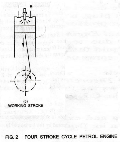
During
this stroke, both the valves remain closed. Due to the rise in pressure, piston
is pushed down with a great force. The hot burnt gases expand pushing the
piston from TDC to BDC. It is also called Working Stroke as work is done by the
expansion of hot gases.
See Fig. 3. The expansion stroke is theoretically represented by the curve 4-5 in the PV Diagram.
At
or near the end of the expansion stroke, the exhaust valve opens to release the
burnt gases to the atmosphere. This suddenly brings down the cylinder to
atmospheric pressure.
This drop in pressure at constant volume is theoretically represented by the vertical line 5-2 in the PV Diagram as shown in Fig. 3.
4. Exhaust Stroke:
Fig. 2(d)
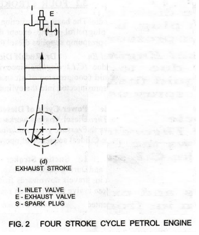
During
this stroke, the exhaust valve opens, as piston moves from BDC to TDC. This movement
of the piston pushes out the exhaust gases from the cylinder. The exhaust gases
are exhausted through the exhaust valve into the atmosphere.
See
Fig. 3.

The
exhaust stroke is theoretically represented by the horizontal line 2-1 in the
PV Diagram.
Uses:
Four stroke petrol engines have higher load carrying capacities than two stroke
petrol engines. Hence, they are used in high power – high speed motor cycles
and passenger cars.
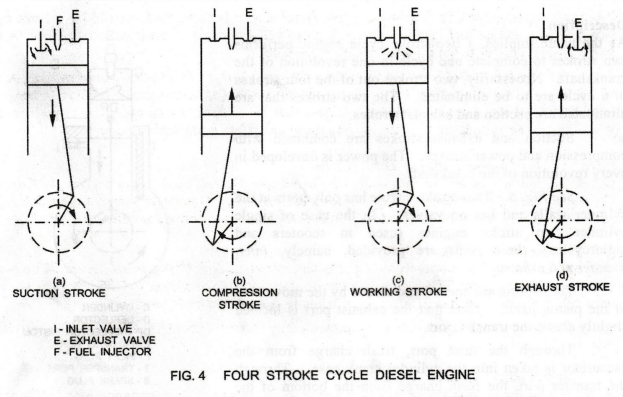
2. FOUR STROKE DIESEL ENGINE
The
basic construction of a four stroke cycle diesel engine is the same as that of
four stroke cycle petrol engine, except that instead of a spark plug, a fuel
injector in mounted in its place. A fuel pump supplies diesel to the injector
at higher pressure.
Dr.
Rudalf Diesel invented the Diesel Engine. It is also known as Compression
Ignition (C.I.) Engine, since ignition takes place due to the high temperature
produced during the compression of air in engine cylinder. Liquid fuel, i.e.,
diesel, which cannot be vapour-ized, is injected into the cylinder in the form
of fine spray using fuel pump and injector.
Power Cycle of Diesel Engine -
Diesel Cycle
Diesel engine works on the principle of
Theoretical Diesel Cycle, also known as Constant Pressure Heat Addition Cycle.
Fig. 5 shows the Pressure Velocity Diagram of the same. The ideal sequence of
operation for the four stroke C.I. engine is explained as follows:
1. Suction Stroke: Fig.
4(a)
During
suction stroke, inlet valve (I) opens and exhaust valve (E) remains closed. The
piston travels downwards from TDC. Air is drawn in, from outside to fill the
cylinder through the inlet valve till the piston reaches BDC. The air taken in
is at atmospheric pressure.
Suction
stroke is theoretically represented by the horizontal line AB in the PV Diagram
in Fig. 5.
2. Compression Stroke:
Fig. 4(b)
At the end of the suction stroke, both the
inlet and the exhaust valves remain closed. The piston moves upwards from BDC
to TDC. The air sucked in during suction stroke is compressed to a high
pressure (35 – 40 bar) and temperature with a decrease in volume. These two
strokes, viz., suction stroke and compression stroke complete one revolution of
the crankshaft.
The
compression stroke is theoretically represented by the curve BC in Fig. 5.
3. Expansion or Power or Working
Stroke: Fig. 4(c)
Just
before the beginning of this stroke, fuel (diesel) is injected in the form of
fine spray into the cylinder through the Fuel Injector. At this moment, the
fuel is ignited by the temperature of the hot compressed air and it starts
burning at constant pressure.
Due
to the high compression ratio of 16 to 20, the temperature at the end of
compression stroke is more than 550°C. This temperature is sufficient to ignite
the fuel, injected into the combustion chamber. The fuel is continuously
injected for 20% of the expansion stroke.
The
ignited air-fuel mixture expands and forces the piston downwards from TDC to
BDC. During this constant pressure expansion stroke, both the valves remain
closed.
See
Fig. 5. This constant pressure expansion with simultaneous combustion is
theoretically represented by the horizontal line CD in the PV Diagram.
The piston is forced further during the remaining part of the expansion stroke due to the expansion of the burnt gases. [The linear motion of the piston causes the piston to produce the mechanical work during this stroke.]
As
the piston moves, the pressure of the hot gases gradually decreases. The
expansion of the burnt gases is theoretically represented by the curve DE in
the PV Diagram as in Fig. 5.

At
the end of the outstroke, the exhaust valve opens. Some of the burnt gases
escape into the atmosphere from the cylinder through the exhaust outlet at
constant volume. This is theoretically represented by the vertical line EB
4. Exhaust Stroke:
Fig. 4(d)
During
the exhaust stroke, the inlet valve is closed and the exhaust valve is opened.
The piston is on its upstroke from BDC to TDC, forcing the burnt gases out of
the cylinder through the exhaust valve.
See Fig. 5.
The
exhaust stroke is theoretically represented by the horizontal line BA.
Expansion and exhaust stroke complete one revolution of the crankshaft. This
completes the cycle and the engine cylinder is ready to suck the fresh air once
again.
Uses:
They are used in heavy-duty transport vehicles such as trucks, tractors,
bulldozers, etc., power generation, industrial and marine applications.
Basic Civil & Mechanical Engineering: UNIT IV: g. Internal combustion engines : Tag: : Petrol, Diesel Engine | Cycle of operation, Classification - Four Stroke Cycle Engines
Related Topics
Related Subjects

Basic Civil and Mechanical Engineering
BE3255 2nd Semester 2021 Regulation | 2nd Semester EEE Dept 2021 Regulation