Basic Civil & Mechanical Engineering: UNIT IV: g. Internal combustion engines
Fuel supply systems
Internal combustion engines | Petrol, Diesel Engine
Function of the Fuel Supply System is to store the fuel required for the engine in a tank and to supply it to the cylinder for combustion.
FUEL SUPPLY
SYSTEMS
Function
of the Fuel Supply System is to store the fuel required for the engine in a
tank and to supply it to the cylinder for combustion.
Combustion
is a chemical process in which oxygen combines with hydrocarbons of the fuel
while burning. Therefore, the fuel has to be thoroughly mixed up with air. In
gaseous fuels, it is easier to mix the gas with the air. However, in liquid
fuels, it has to be vapourized or atomized. Vapourization is a change of state
of the fuel from liquid state to vapour state. But, atomization is a mechanical
breaking up of the fuel into minute particles.
For
liquid fuels, there are two methods of mixing the fuel with air, namely,
Carburetion and Injection. The mode of entry of fuel into the engine cylinder
from the petrol (Spark Ignition) engine and diesel (Compression Ignition)
engine are different.
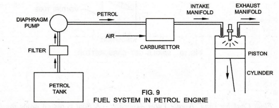
1. FUEL SUPPLY SYSTEM IN PETROL ENGINE
Fuel
system in a petrol engine consists of: Fuel tank, Fuel gauge, Fuel filter, Fuel
pump and Carburettor. The fuel gauge indicates the fuel level in the fuel tank.
The fuel passes through a fine hole in the carburettor to the combustion
chamber of the engine cylinder through the inlet valve. As petrol passes
through a fine hole in the carburettor, it is filtered.
Petrol
from the fuel tank may be delivered to the carburettor by gravity or pressure.
In the gravity feed system, the fuel tank is placed above the carburettor. In
the pressure feed system, a small capacity diaphragm pump is provided to pump
the petrol from the fuel tank by a cam mechanism driven by the crankshaft. See
Fig. 9.
Carburettor
Carburettor: Carburettor is considered as the
heart of petrol engine. It is a device for atomizing and vapourizing the
volatile liquid fuel (petrol) and mixing it with air. It is attached to the
intake manifold connected with the engine cylinder. Carburetion: In the S.I.
engine, a combustible petrol-air mixture is prepared outside the engine
cylinder. The process of vapourizing the fuel (petrol) and mixing it with air
outside the cylinder in the S.I. engine is known as Carburetion.
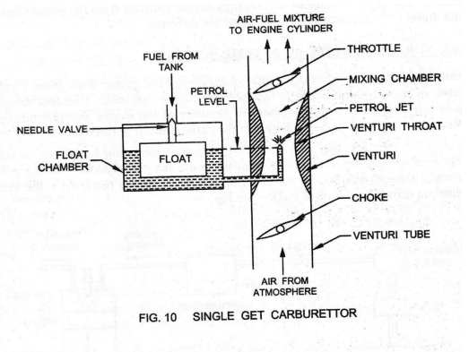
Single Jet Carburettor: (Fig. 10)
Functions of the Carburettor
1. The carburettor vapourizes and atomizes
petrol and mixes it thoroughly with air at the proportion of 15 parts of air
and 1 part of petrol vapour by mass. The reason is that: with less air, some
portion of the fuel will remain un-burnt due to insufficient supply of oxygen while
with excess air, the rate of burning will be slower.
2.
For running at higher speeds and for starting the engine, we need rich mixture
with air-fuel ratio in the range of 10 – 12. For this, the carburettor
regulates the amount of air-fuel mixture (throttles) entering into the cylinder.
3. Provision is made for easy starting (choke)
in cold weather.
Description
1. Float, Float Chamber and Needle Valve
Assembly: A float is placed inside the float chamber. The
level of petrol in the float chamber is maintained constant and slightly below
the top of the petrol jet by the float and needle valve arrangement.
2. Petrol Jet:
The Petrol Jet is connected to the float chamber. If the amount of petrol in
the float chamber falls below the required level (This is possible if the
supply from the fuel tank to the float chamber is less than the fuel supplied
by the jet. This happens when the load on the engine increases), the float
lowers. The needle valve is opened for increased fuel supply from the fuel
tank. When the required level is reached, the float closes the needle valve.
As
the level of fuel in the float chamber rises (This is possible if the supply
from the fuel tank to the float chamber is more than the fuel supplied by the
jet. This happens when the load on the engine decreases), the float also rises.
The needle valve closes the fuel inlet and a constant level is maintained.
3. Venturi and Venturi Throat:
Venturi is a tube of decreasing cross-section which reaches a minimum at the
throat, called Venturi Throat.
4. Throttle:
The control of the throttle is normally with the accelerator pedal.
5. Choke:
Choke is provided in the air passage before the venturi.
Working Principle
During suction stroke, air flows through the
choke valve and passes through the venturi. Its velocity increases and pressure
decreases in the venturi throat due to reduction in area.
Because
the pressure at the float chamber is atmospheric and that at the tip of the
petrol jet (i.e., throat) below atmospheric, a pressure differential called
carburettor depression exists between them. This causes the flow of fuel from
the float chamber through the jet in fine spray into the air-stream. The fuel
gets vapourized and an uniform air-fuel mixture is supplied to the cylinder. At
normal speed, the carburetor delivers a normal mixture of air-fuel ratio 15:1.
The
quantity of mixture supplied to the cylinder is controlled by the throttle
connected to the accelerator. As the throttle is closed, less air flows through
the venturi and less is the quantity of air-fuel mixture delivered to the
cylinder. Hence, less power is developed. As the throttle is opened, more
quantity of air-fuel mixture is delivered to the cylinder. Thus, the engine
speed can be changed by controlling the amount of air-fuel mixture by means of
the throttle.
Choke
Choke is necessary to provide an extra-rich
mixture than the usual mixture ( i.e., almost 5 to 10 times more fuel ) to the
engine during starting or warm up in cold weather. This is done by partly
closing the choke and reducing the flow of air during starting or warming.
Limitations of Single Jet
Carburettor
1. It gives proper mixture at only one engine
speed and load. Therefore, it is suitable only for engines running at constant
speeds and loads.
2. The working of a single jet carburetor is
affected by changes of atmospheric pressure. At high altitudes, due to less
density of air, rich mixture is unnecessarily available.
3. Starting is difficult.
4.
Automatic control of the air-fuel ratio is not possible due to climatic
changes.
In
Modern carburettors, multi-jets are provided for climatic and altitude
corrections.
2. FUEL SUPPLY SYSTEM FOR DIESEL ENGINE
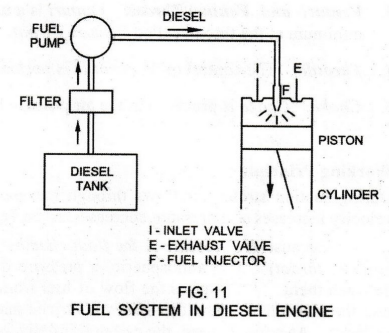
See
Fig. 11. Fuel System for Diesel Engine consists of: Fuel tank, Fuel level
indicator, Fuel filter, Fuel pump and Fuel injector or Atomizer.
In
the diesel engine, diesel is to be injected in the compressed air at high pressure
(compression ratio 16 to 20). So, it is necessary to increase the fuel pressure
using fuel pump.
Fuel
Tank serves as the main fuel reservoir. Fuel Filter is used to remove the dirt
and impurities in the fuel before entering the fuel pump.
Fuel
Pump draws fuel from the filter and supplies it at high pressure to the fuel
injector.
Fuel
Injector is having fine holes at its tip. It is used to atomize and inject the
fuel into the combustion chamber.
DIESEL FUEL PUMP:
Fig. 12
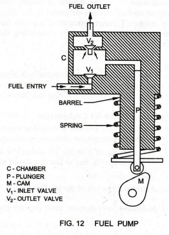
Working Principle
See Fig. 12. Fuel pump consists of a plunger
working in a barrel. The plunger is moved up against the action of a spring by
means of a cam.
When
the plunger moves in the downward direction due to the action of the spring,
the fuel comes into the chamber through the inlet valve from the fuel tank.
When
the cam rotates, the plunger moves in the upward direction against the compression
of the spring. The fuel is now compressed to a pressure higher than that of
engine cylinder at the end of compression. The fuel at high pressure is forced
through the outlet valve from the chamber to the fuel injector.
The
fuel pump also controls the quantity of fuel pumped for different speeds and
loads, by varying the stroke of the plunger.
Fuel Injector (Fig. 13)
Working Principle
Fuel Pump delivers an accurately metered
quantity of fuel under high pressure at the correct moment to the Fuel Injector.
The high pressure fuel from the fuel pump is injected into the cylinder with
the help of the fuel injector. The functions of the fuel injector are:
-
To inject the fuel into the engine cylinder by atomizing the fuel to the
required degree;
-
To distribute the fuel such that there is rapid and complete mixing of fuel and
air.
Fig.
13 shows a typical Bosch Fuel Injector or Fuel Atomizer. It consists of:
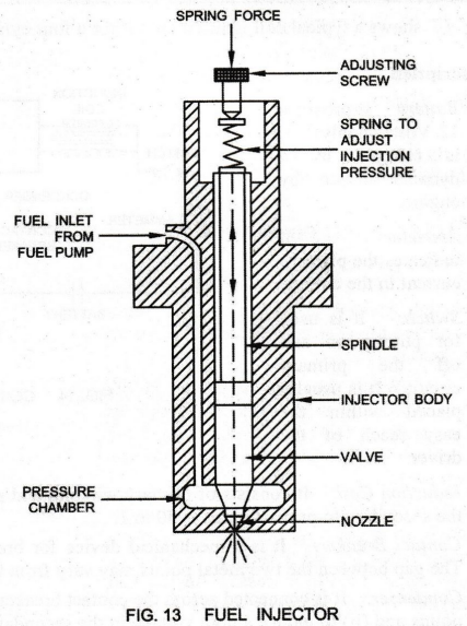
1.
Injector Body
2.
Spring
3. Adjusting Screw
4. Spindle
5.
Fuel Inlet
6.
Valve
7.
Pressure Chamber
8. Nozzle
The
high-pressure fuel from the fuel pump enters into the fuel injector through the
Fuel Inlet. Then, it enters the Pressure Chamber.
The
fuel acts on the Valve from the bottom. The valve is kept in the seat by a helical
spring. The valve is lifted up due to the high pressure of the fuel against the
Spring Tension.
When
the valve is lifted up, the fuel rushes out through the fine nozzle hole in an
atomized form. Atomized fuel is now injected into the combustion chamber of the
engine cylinder in the form of fine spray and it rapidly mixes with the
compressed air.
As
the pressure of the fuel falls, the spring presses the spindle. The valve comes
back to its seat and is automatically closed by the spring force. The tension
of the spring can be adjusted manually by means of the Adjusting Screw at the
top.
Basic Civil & Mechanical Engineering: UNIT IV: g. Internal combustion engines : Tag: : Internal combustion engines | Petrol, Diesel Engine - Fuel supply systems
Related Topics
Related Subjects

Basic Civil and Mechanical Engineering
BE3255 2nd Semester 2021 Regulation | 2nd Semester EEE Dept 2021 Regulation