Transmission and Distribution: Unit II: (a) Modelling and Performance of Transmission Lines
Generalised Circuit Constants of a Transmission Line
The transmission system can also be assumed to be a four terminal network with two input terminals where power enters the network and two output terminals where power leaves the network.
Generalised Circuit
Constants of a Transmission Line
AU: Oct.-01, May-04, 11, 15, Dec.-03,
04, 06, 10, 11, 13
Consider a two port network shown in the
Fig. 2.9.1.
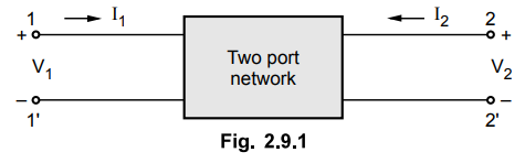
The above network is a four terminal
network with 4 variables;
two on input side and two on output
side. V1 and I1 are the voltage and current on input side whereas V2 and I2 are the voltage and current on output side.
The transmission system can also be
assumed to be a four terminal network with two input terminals where power
enters the network and two output terminals where power leaves the network.
Let VS
= Sending end voltage, IS = Sending end current
VR = Receiving end voltage, IR
= Receiving end current
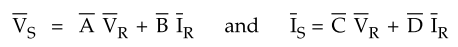
The sending end voltage and current can
be expressed in terms of receiving end voltage and current through the set of
parameters known as transmission line parameters or ABCD parameters. Thus we
have,
The network between the transmission
line should be linear, passive and bilateral. The parameters 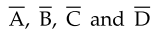 which
are generally complex numbers are the constants also known as generalised
circuit constants. The method which is used for analysis of transmission line
has influence on these constants. With the knowledge of these constants,
performance calculations of the line can be easily obtained.
which
are generally complex numbers are the constants also known as generalised
circuit constants. The method which is used for analysis of transmission line
has influence on these constants. With the knowledge of these constants,
performance calculations of the line can be easily obtained.
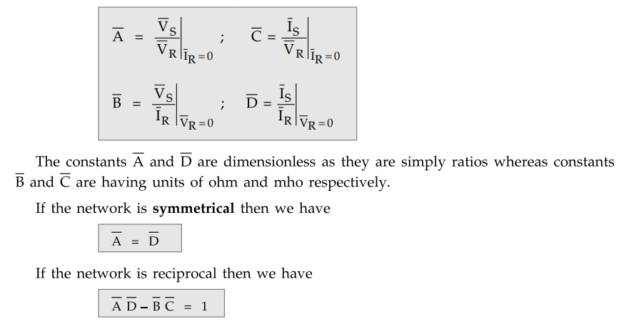
These parameters are given by
Now we will find these constants in case
of short and medium transmission line.
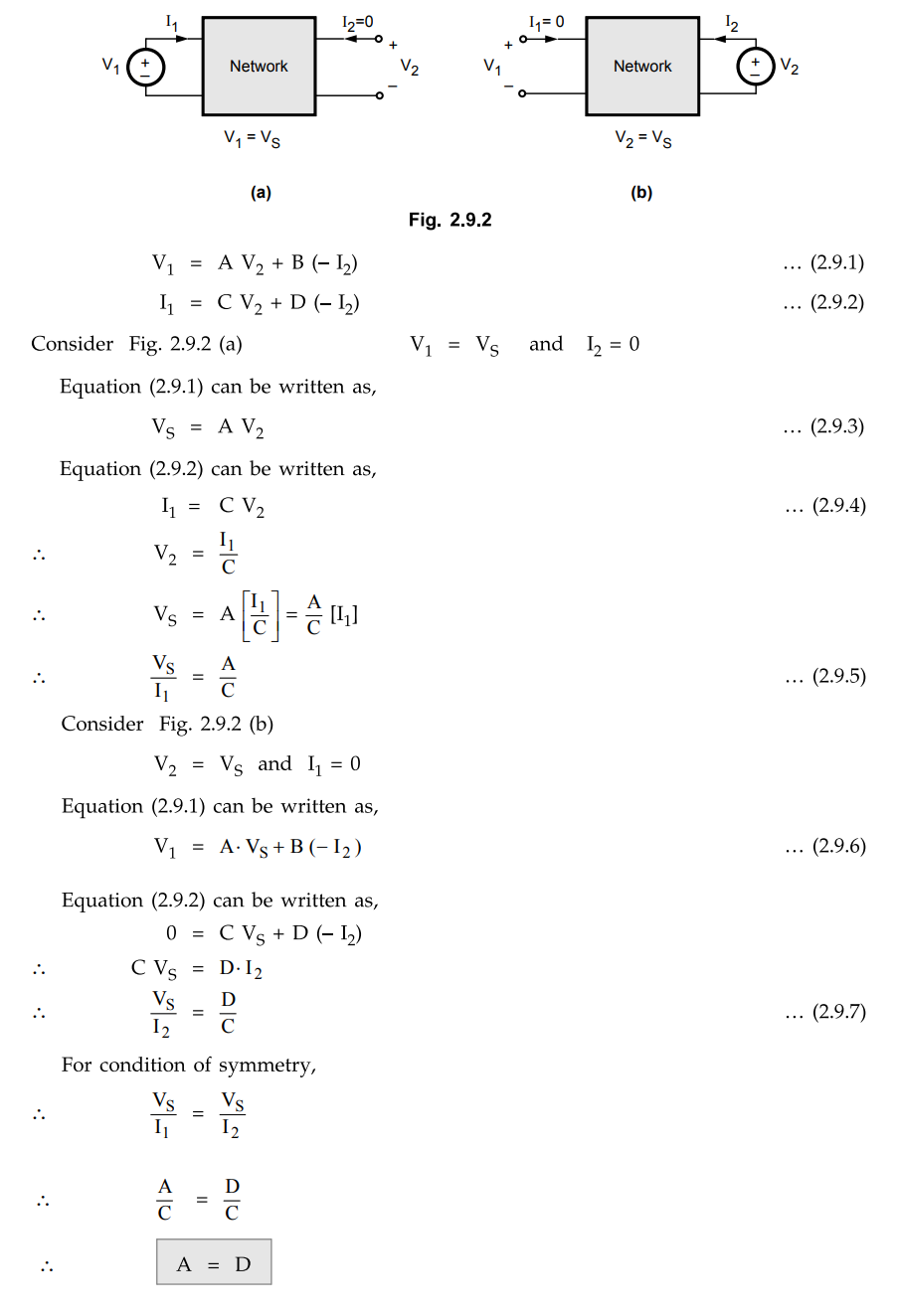
1. Condition of Symmetry for Transmission Parameters
The basic equations for the transmission
parameters are as following,
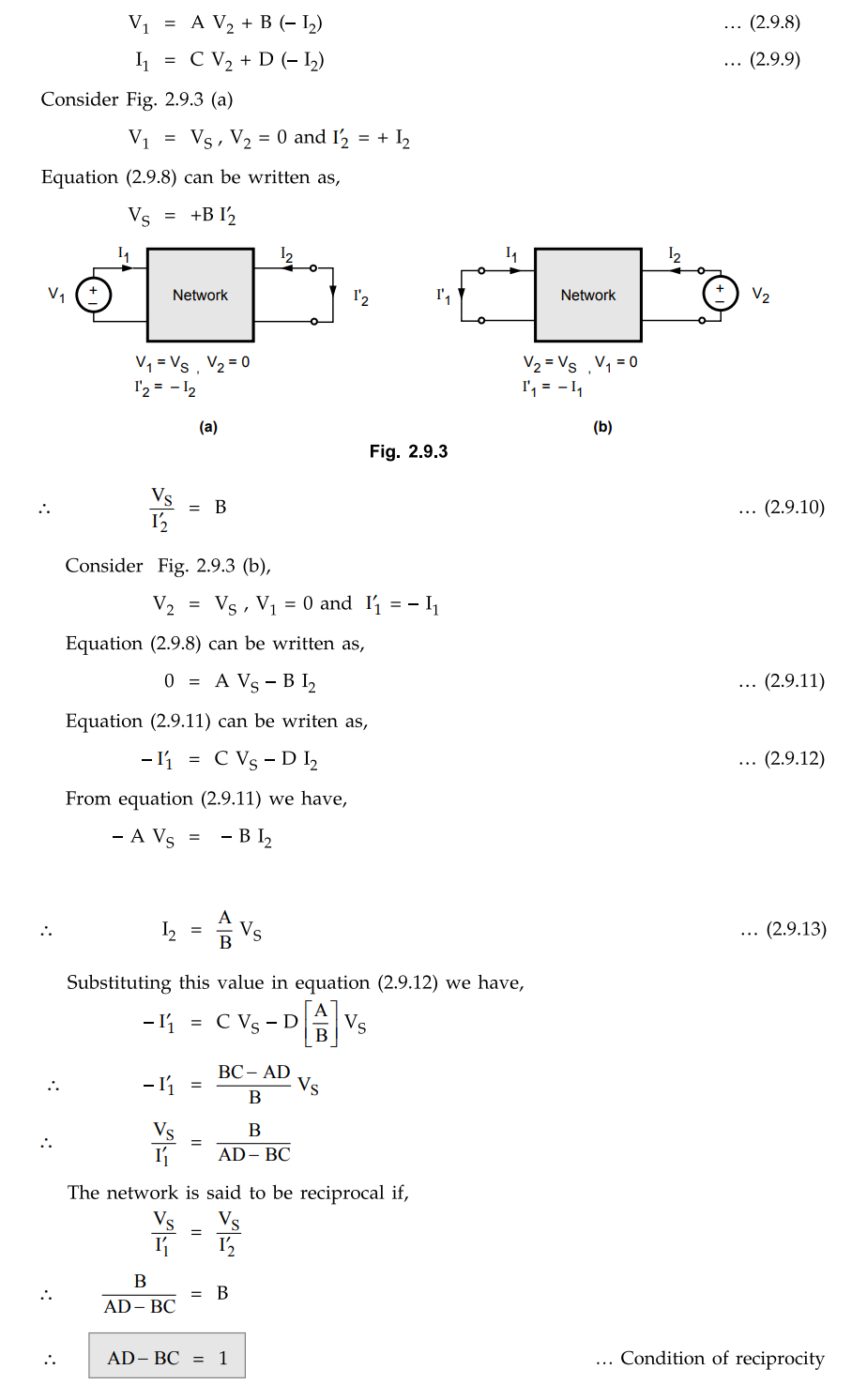
2. Condition of Reciprocity for ABCD Parameters
The basic equations for ABCD parameters
are as follows,
3. Short Transmission Line
The short transmission line is
represented in the Fig. 2.9.4. In case of short transmission line, the effect
of the line capacitance is neglected. The line is having the series impedance.
In the figure only one phase is shown from the three phases.
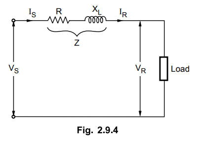
We have,
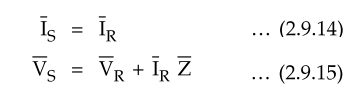
The defining equations for transmission
line parameters are
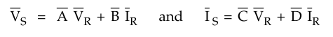
Comparing equations (2.9.14) and
(2.9.15) with the standard equations written above we have
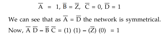
Thus the network is seen to be
reciprocal also.
4. Medium Transmission Line
a.
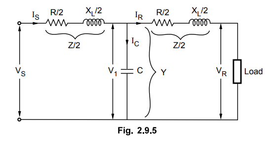
Nominal T Method
In nominal T method of analysis of
medium transmission line the total line capacitance is assumed to be lumped or
concentrated at the center point of the line whereas half the line resistance
and reactance are lumped on either side of the line. This is shown in the Fig.
2.9.5.
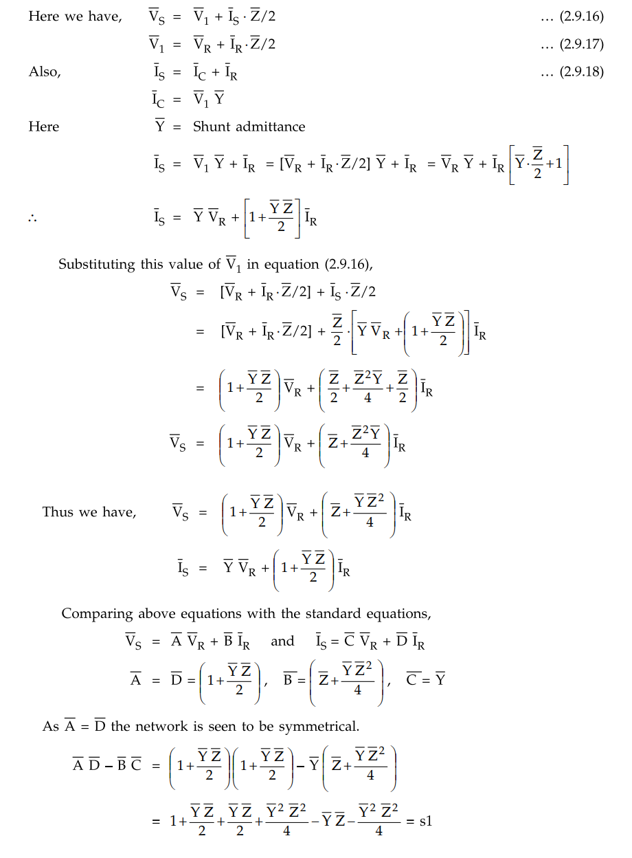
The network is seen to be reciprocal
also.
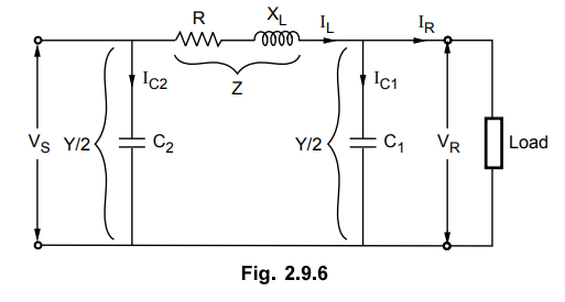
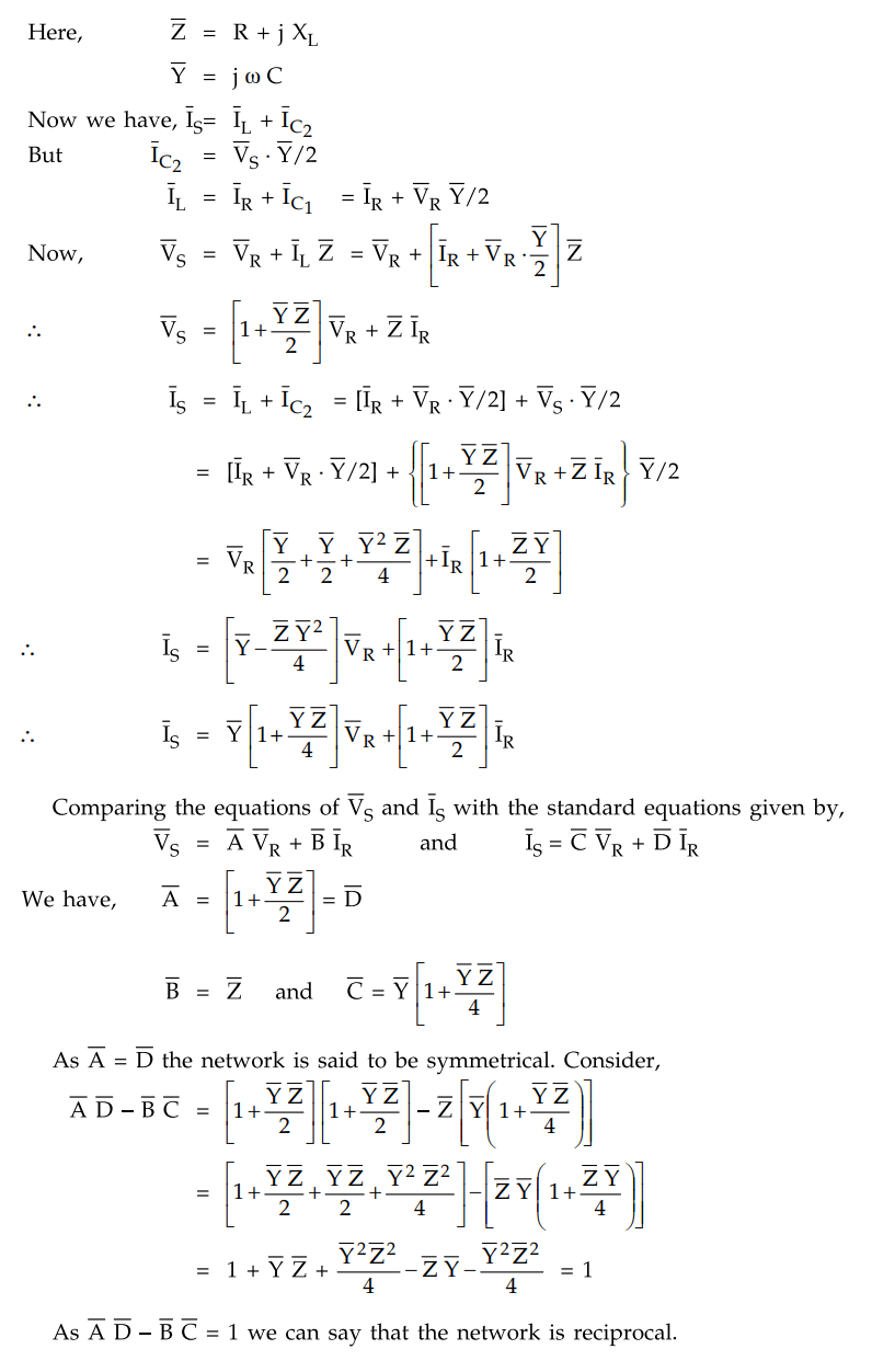
b. Nominal π Method
In nominal π method, the total
capacitance is divided into two halves with one half at the receiving end and
the other half at the sending end. This is shown in the Fig. 2.9.6.
Example 2.9.1
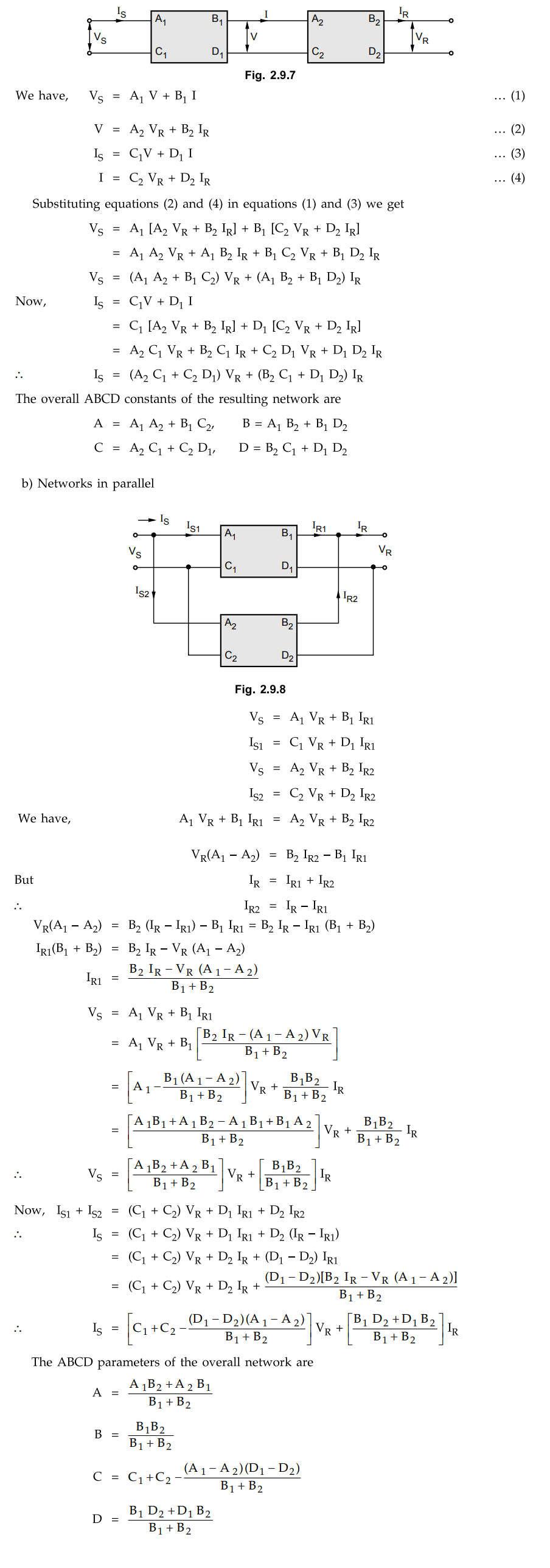
Two transmission lines having generalised circuit constants A1 ,
B1, C1, D1 and A2, B2, C2,
D2 are connected in a) series b) parallel.
Derive expression for overall ABCD
constants of the resulting network.
Solution : a)
Networks in series
Example 2.9.2
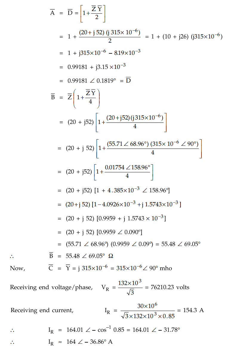
A balanced. 3 phase load of 30 MW is supplied at 132 kV, 50 Hz and 0.85 p.f.
lagging by means of a transmission line. The series impedance of a single
conductor is (20 + j 52) Ω and the total phase-neutral admittance is 315 x 10_6
mho. Using nominal T method determine :
i) The A, B, C and D constants of the
line ii) Sending end voltage iii) Regulation of the line.
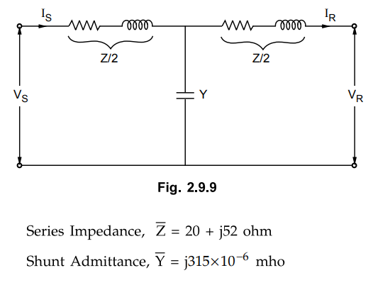
Solution :
Fig.
2.9.9 shows a representation of a transmission line using nominal T method.
Now ABCD constants of a transmission
line are given by,
Receiving end voltage VR is
taken as reference
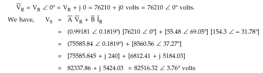
Sending end voltage per phase = 82.516
kV
Sending end line voltage = √3 × 82.516 =
142.92 kV
Voltage regulation is nothing but change
in voltage at receiving end from no load to full load.
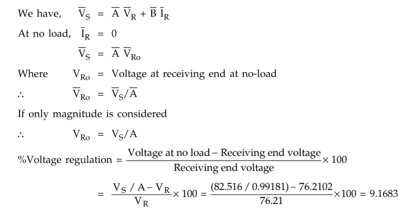
Voltage regulation = 9.168 %
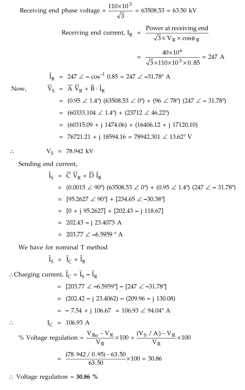
Example 2.9.3
A 110 kV, 50 Hz, 3 phase transmission line delivers a load of 40 MW at 0.85
lagging p.f. at the receiving end. The generalised constants of the
transmission line are
A = D = 0.95∠ 1.4°
B = 96 ∠ 78° ohm
C = 0.0015 ∠ 90° mho
Find the regulation of the line and
charging current use nominal T method.
Solution :
Receiving end voltage, VR = 110 kV
Example 2.9.4
The generalised circuit constants of a transmission line are
A = 0.93 + j 0.016
B = 20 + j 140
The load at the receiving end is 60 MVA,
50 Hz at 0.8 p.f. lagging. The voltage at the supply end is 220 kV. Determine
the load end voltage.
Solution :
Given that,
VS = 220 kV 220
Phase value,VS = 220 / √3 = 127 kV
Let the receiving end voltage per phase
VR which is taken as reference vector
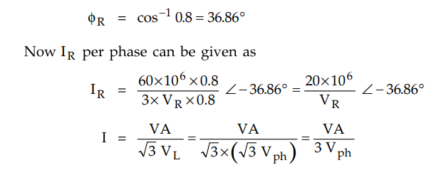
As VR is phase voltage while calculating
I, factor 3 is used in the denominator.
Now we have B = 20 + j 140 = 141.421 ∠ 81.8698
The
sending end voltage is given by,
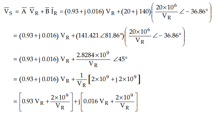
Although we are not knowing the angle
associated with VS we will consider only magnitude of VS.
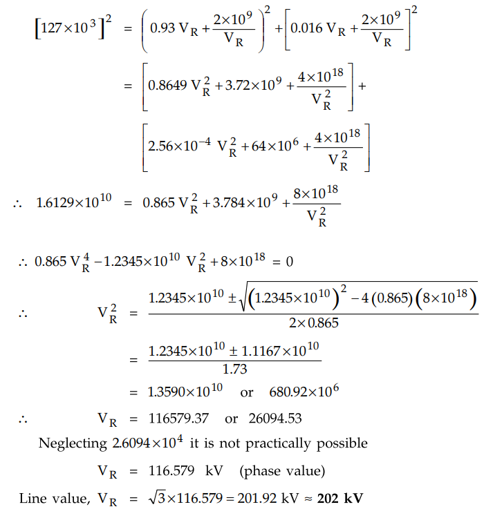
|VS| = 127 kV per phase.
Review Questions
1. What are ABCD constants ?
2. Determine the generalized circuit constants of short
transmission line. State the characteristics of it. Also prove that short
transmission line behaves like a symmetrical network.
3. Derive the relationship between sending end and
receiving end quantities in terms of voltage and current for 'Tee' circuit
medium transmission line.
4. Express the relationship for the sending end voltage and
current in terms of receiving end voltage and current for a medium length
transmission line with nominal pi method of representation. Evaluate the
generalised circuit constants.
5. Determine the generalized circuit constants of medium
transmisison line. Also prove that the transmission line behaves like a
symmetrical network and reciprocal network.
6. Derive an expression for ABCD constants of a medium
transmission lines using nominal T method. Show that AD - BC = 1.
7. Derive the values of generalised network constants A, B,
C and D using nominal n equivalent circuit for medium transmission line.
8. A balanced 3 phase load of 30 MW is supplied at 132 kV,
50 Hz and 0.8 p.f. lagging by means of a transmission line. The series
impedance of a single conductor is (20 + j 52) Ω and the total phase-neutral
admittance is 315 ×10-6 mho. Using nominal T method determine, i)
The A, B, C and D constants cf the line ii) Sending end voltage.

9. A 110 kV, 50 Hz, 3 phase transmission line delivers a
load of 40 MW at 0.85 lagging p.f. at the receiving end. The generalised
constants of the transmission line are A = D = 0.95 ∠ 1.4°, B = 96 ∠ 78° ohm, C = 0.0015 ∠ 90° mho. Find the regulation of the line and charging
current, use nominal T method.
[Ans.: 30.86%, 106.93]
10. Find the following for a single circuit transmission
line delivering a load of 45 MVA at 352 kV and p.f. 0.8 lagging.
1) Sending end voltage
2) Sending end curent
Given values are A = C = 0.99 ∠ 0.3°; B = ∠ 69° ohms, D = 4.0 ×10-
4 ∠ 90°, where Es = AEr + BIr
and IS = CIr + DEr
[Ans.: 87.42 kV, 178.34 A]
Transmission and Distribution: Unit II: (a) Modelling and Performance of Transmission Lines : Tag: : - Generalised Circuit Constants of a Transmission Line
Related Topics
Related Subjects

Transmission and Distribution
EE3401 TD 4th Semester EEE Dept | 2021 Regulation | 4th Semester EEE Dept 2021 Regulation