Digital Logic Circuits: Unit IV: (b) Hazards and Errors in Digital Circuits
Hazards in sequential circuits
• The unwanted switching transients (glitches) that may appear at the output of a circuit are called Hazards.
Hazards
AU
: Dec.-12, 14, 17, 18, May-16, 17
•
The unwanted switching transients (glitches) that may appear at the output of a
circuit are called Hazards. The hazards cause the circuit to malfunction. The
main cause of hazards is the different propagation delays at different paths.
Hazards occur in the combinational circuits, where they may cause a temporary
false output value. When such combinational circuits are used in the
asynchronous sequential circuits, they may result in a transition to a wrong
stable state.
•
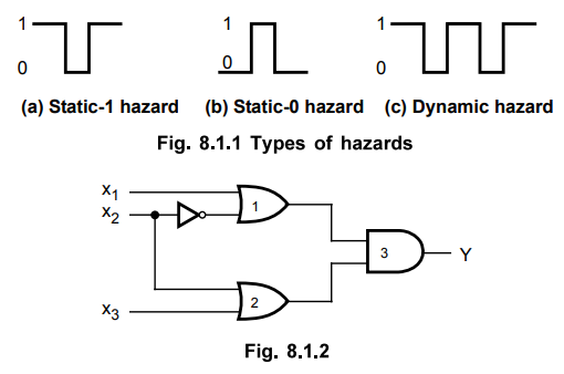
There are two types of hazards : Static hazards and dynamic hazards. A static
hazard exists if a signal is supposed to remain at particular logic value when
an input variable changes its value, but instead the signal undergoes a
momentary change in its required value. According to definition, the static
hazards are further classified as static-0 hazard and static-1 hazard.
•
In a combinational circuit, if output goes momentarily 0 when it should remain
a 1, the hazard is known as static-1 hazard. On the other hand, if output goes
momentarily 1 when it should remain a 0, the hazard is known as static-0
hazard. Another type of hazard is dynamic hazard in which output changes three
or more times when it should change from 1 to 0 or from 0 to 1. The Fig. 8.1.1
shows the three types of hazards.
•
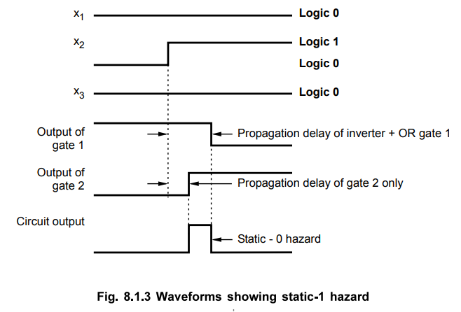
The Fig. 8.1.2 shows circuit with hazards. Assume that, initially, inputs x1
, x2 and x3 = 0. This causes the output of gate 1 to be
1, that of gate 2 to be 0, and the output of the circuit to be equal to 0. Now
consider change in x2 from 0 to 1. The output of gate 1 changes to 0
and that of gate 2 changes to 1, leaving the output at 0. However, the output
momentarily goes to 1 if the propagation delay through the inverter is taken
into consideration. The delay in the inverter causes the output of gate 2 to
change to 1 before the output of gate 1 changes to 0. In this situation, both
inputs of gate 3 are momentarily equal to 1, causing the output to go to 1 for
the short time equal to the propagation delay of the inverter. This is
illustrated in the Fig. 8.1.3.
1. Eliminating a Hazard
•
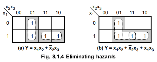
The hazard exists because of the change of input results in a different product
terms covering two minterms or different sum terms covering two maxterms.
Whenever the circuit move from one product term to another or move one sum term
to another, there is a possibility of a momentary interval when neither term is
equal to 1, giving rise to an undesirable 0 output. Hazards can be eliminated
by enclosing two minterms or maxterms in question. For example, if the circuit
has minterms 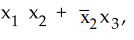 , then these two minterms must be enclosed by introducing
another minterm x^. This is illustrated in Fig. 8.1.4.
, then these two minterms must be enclosed by introducing
another minterm x^. This is illustrated in Fig. 8.1.4.
Ex.
8.1.1 Find a way to remove the hazard in product of sums expression given by
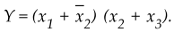
AU
: Dec.-12, Marks 4
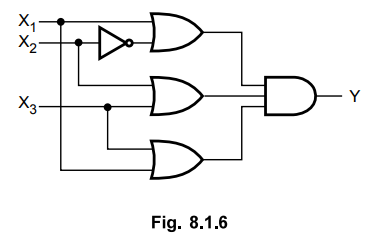
Sol. :
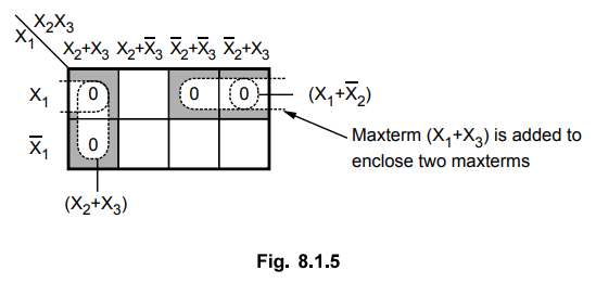
Thus,
we can eliminate hazard by adding one more OR gate as shown in Fig. 8.1.6.
Ex.
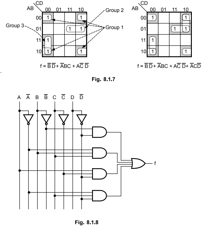
8.1.2 Give hazard-free realisation for the following Boolean function,
f (A, B,C,D) = ^m (0, 2, 6, 7, 8, 10, 12)
Sol.
: The given function can be implemented using K-map as shown in the Fig. 8.1.7
and Fig. 8.1.8 shows the additional product term,  D overlapping two groups
(group 1 and group 2) for hazard free realization. Group 1 and group 3 are
already overlapped hence they do not require additional minterm for grouping.
D overlapping two groups
(group 1 and group 2) for hazard free realization. Group 1 and group 3 are
already overlapped hence they do not require additional minterm for grouping.
2. Hazards in Sequential Circuits
• We know that, in sequential circuits, the combinational circuits are associated with them to drive the flip-flop inputs. In synchronous sequential circuits, the hazards due to combinational circuits associated with them are not of concern. This is because momentary erromeous signals are not generally troublesome in synchronous circuits. However, if a momentary incorrect signal is fed back in an asynchronous sequential circuit, it may cause the circuit to go to the wrong stable state.
•
Let us consider the logic diagram and its transition table as shown in Fig.
8.1.9. For the circuit shown in Fig. 8.1.9, if the circuit is in total stable
state YX1X2 = 111 and input X2 changes from 1
to 0, the next total stable state should be YX1X2 = 110.
However, because of hazard, the output Y may go to 0 momentarily. If this false
signal feeds back into AND2 before the output of the inverter goes to 1, the
output of AND2 will remain at 0 and the circuit will switch to the incorrect
total stable state 010.

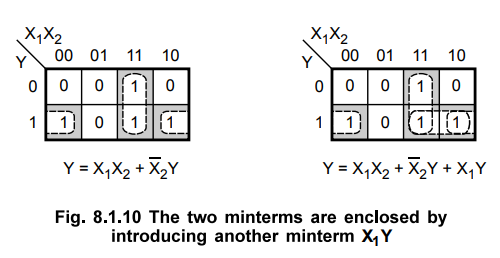
•
Such a hazard can be eliminated by enclosing two minterms by another minterm as
shown in the Fig. 8.1.10.
•
Therefore, the hazard free asynchronous sequential circuit will be as shown in
Fig. 8.1.11.

3. Essential Hazards
•
In the previous section we have seen static and dynamic hazards and remedies to
remove it. There is another type of hazard that may occur in asynchronous
sequential circuits, called essential hazards. An essential hazard is caused by
unequal delays along two or more paths that originate from the same input. Such
hazards can be eliminated by adjusting the amount of delays in the affected path.
Review Questions
1. What are hazards in asynchronous sequential circuits ?
2. What are hazards in sequential circuits ? How can they be
eliminated ?
AU : Dec.-12, Marks 6
3. Explain the various types of hazards in sequential circuit
design and the methods to eliminate them. Give suitable examples.
4. What are static - 0 and static - 1 hazards? Explain the
removal of hazards using hazard covers in K-map
AU : May-16, Marks 8
5. Illustrate about hazards in sequential circuits and the steps
to avoid hazards in it.
AU : Dec.-18, Marks 13
Digital Logic Circuits: Unit IV: (b) Hazards and Errors in Digital Circuits : Tag: : - Hazards in sequential circuits
Related Topics
Related Subjects

Digital Logic Circuits
EE3302 3rd Semester EEE Dept | 2021 Regulation | 3rd Semester EEE Dept 2021 Regulation