Electrical Machines: Unit III: b.Testing of D.C. Machines
Hopkinson's Test
Advantages, Disadvantages, Solved Example Problems | Testing of D.C. Machines
• This test is called regenerative test or back to back test which can be carried out on two identical d.c. machines mechanically coupled to each other and simultaneously tested.
Hopkinson's
Test
AU: Dec.-05,06,08,09,16,19,
May-07,14,16
•
This test is called regenerative test or back to back test which can be carried
out on two identical d.c. machines mechanically coupled to each other and
simultaneously tested. Thus the full load test can be carried out on two
identical shunt machines without wasting their outputs. One of the machines is
made to act as a motor while the other as a generator. The mechanical output
obtained from the motor drives the generator whose electrical output supplies
the greater part of input to the motor. The motor is connected to the supply
mains only to compensate for losses since in absence of losses, the
motor-generator set would have run without any external power supply. But due
to losses, the generator output is not sufficient to drive the motor. Thus
motor takes current from the supply to account for losses.
•
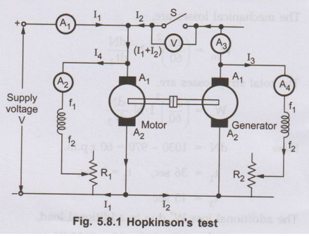
The Fig. 5.8.1 shows the connection diagram for Hopkinson's test. The two shunt
machines are connected in parallel. One of the machines is then started as a
motor. Here the startor connections are not shown for simplicity.
•
The switch S is kept open. The other machine which is coupled to first will act
as load on first which is acting as motor. Thus second machine will act as a
generator. The speed of motor is adjusted to normal value with the help of the
field rheostat. The voltmeter reading is observed. The voltage of the generator
is adjusted by its field rheostat so that voltmeter reading is zero. This will
indicate that the generator voltage is having same magnitude and polarity of
that of supply voltage. This will prevent heavy circulating current flowing in the
local loop of armatures on closing the swi5ztch. Now switch S is closed. The
two machines can be put into any load by adjusting their field rheostats. The
generator current I2 can be adjusted to any value by increasing the
excitation of generator or by reducing the excitation of motor. The various
readings shown by different ammeters are noted for further calculations.
•
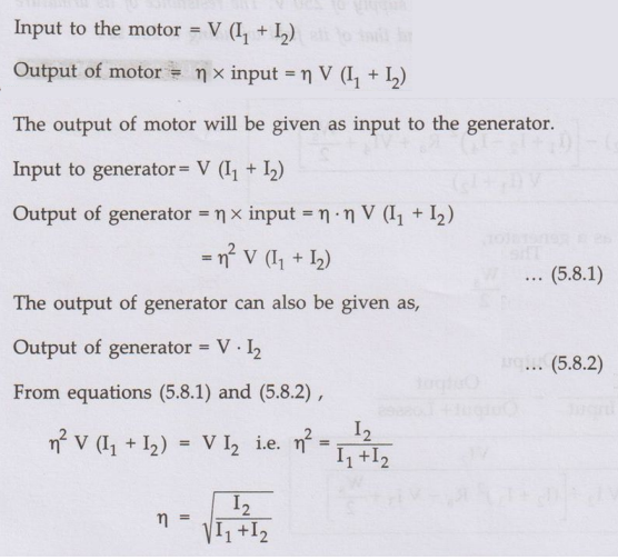
The input to the motor is nothing but the output of the generator and small
power taken from supply. The mechanical output given by motor after supplying
losses will in turn drive the generator.
Let
V = Supply voltage
I1
= Current taken from the supply,
I2
= Current supplied by generator
I3
= Exciting current of generator,
I4
= Exciting current of motor
Ra
= Resistance of armature of each machine
η = Efficiency of both generator and motor.
But
the assumption of equal efficiencies of two machines is true in case of only
large output machines where difference in armature currents of two machines is
not large. Also the difference in excitation current required to circulate full
load current in the armature will not affect the iron losses. But in case of
small machines the difference between armature and field currents is large. So
efficiencies cannot be assumed to be same. Here the stray losses are assumed to
be equal whereas armature and field copper losses are separately determined for
estimating the efficiencies separately.
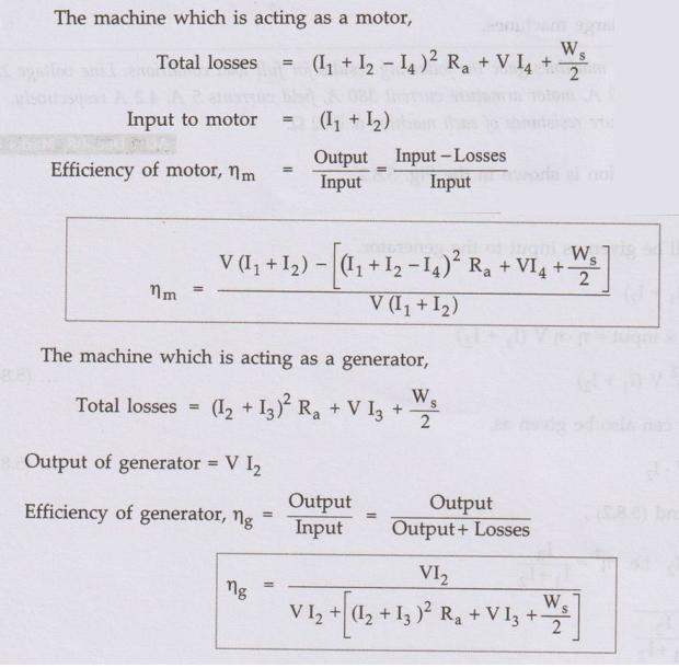
Armature
copper loss in generator = (I2 + I3)2 Ra
Armature
copper loss in motor = (I1 + I2 −14)2
Copper loss in field winding of generator = V I3
Copper
loss in field winding of motor = V I4
But
total losses in generator and motor are equal to the power supplied by the
mains.
Power
drawn from supply = V I2
The
stray losses of both machines can be calculated as, ananigol
Total
stray loss for both the machines = VI2 − [(I2 + I3)2
Ra + (I1 + I2 – I4)2 Ra
+ VI3 + VI4] = Ws(say)
Assuming
that stray losses are equally divided between the two machines.
Stray
loss for each machine = Ws/2
1. Advantages
The
various advantages of Hopkinson's test are,
1.
The power required for conducting the test is small compared to full load
powers of the two machines.
2.
Since the machines are operated at full load conditions, change in iron loss
due to distortion in flux at full load will be included in the calculations.
3.
As the machines are tested under full load conditions, the temperature rise and
quality of commutation of the two machines can be observed.
4.
The test is economical as power required to conduct the test is very small
which is just sufficient to meet the losses.
5.
There is no need for arranging any actual load. Similarly by changing the field
currents of two machines, the load can be easily changed and a load test over
complete range of load can be taken.
2. Disadvantages
The
various disadvantages of Hopkinson's test are,
1.
There is difficulty in availability of two identical machines.
2.
The iron losses in the two machines cannot be separated. The iron losses are
different in both the machines because of different excitations.
3.
The machines are not loaded equally in case of small machines which may lead to
difficulty in analysis.
This
test is better suited in case of large machines.
Ex. 5.8.1
The Hopkinson's test on two shunt
machines gave the following results for full load conditions. Line voltage 250
volts, line current excluding field currents is 50 A, motor armature current
380 A, field currents 5 A, 4.2 A respectively. Calculate the efficiency of each
machine. Armature resistance of each machine is 0.02 Ω AU : Dec. -08, Marks 8
Sol. :
The connections and current distribution is shown in the Fig. 5.8.2.

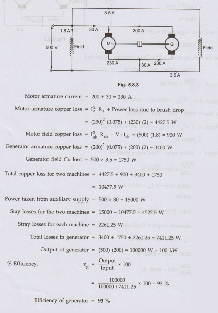
Ex. 5.8.2 In a Hopkinson's test on a pair of 500 V,
100-kW shunt generators, the following data was obtained: Auxiliary supply, 30
A at 500 V: Generator output current, 200 A Field currents, 3.5 A 1.8 A
Armature circuit resistances, 0.075 each machine. Voltage drop at brushes, 2 V
(each machine). Calculate the efficiency of the machine acting as a generator. AU : Dec.-16
Sol. : V = 500 V, P = 1000 kW
Review Questions
1. Explain the
Hopkinson's test for determining efficiency of two similar d.c. shunt machines.
State its merits and demerits. AU: Dec.-06, 09, 19, May-16, Marks 8
2. The following
results were obtained from Hopkinson's test on two similar d.c. machines:
Supply voltage 400 V, line current 50 A. Generator armature current 250 A,
field currents 2.4 and 2.5 A. Estimate the efficiency of each machine on the
loads of the test. Armature resistance of each machine is 0.1 Ω. AU: Dec.-05 (Ans.:
2375 W, 89.72 %, 91.22%)
3. The following
results were obtained during Hopkinson's test on two similar 230 V machines;
armature currents 37 A and 30 A; field currents 0.85 A and 0.8 A. Calculate the
efficiencies of machines if each has armature resistance of 0.33 Ω.
(Ans.: 647.27 W, 481
W, 430.615 W, ηm = 87.61%)
4. Explain back to
back test as two identical DC machines and calculate the efficiency of the
machines as generator and motor. Mention the advantages of this test over the
other tests.
5. The Hopkinson's
test on two shunt machines gave the following results for full load conditions.
Line voltage 250 volts, line current excluding field currents is 50 A, motor
armature current 380 A, gfield currents 5 A, 4.2 A respectively.
Calculate the
efficiency of each machine. Armature resistance of each machine is 0.02 Ω. (Ans.: 92.03 %,
92.02%)
6. The Hopkinson's
test on two similar d.c. shunt machines gave the following results :
Line voltage = 220 V,
Line current excluding field current = 40 A,
Armature current of
motoring machine = 200 A, Field currents 6 A and 7 A.
Calculate the
efficiency of each of the machines at the given load conditions. The armature
resistance of each of the machines is 0.05 Ω. (Ans.: 86.75 %,
85.78%)
7. What are the
merits and demerits of Hopkinson's test ?AU : May-14, Marks 4
Electrical Machines: Unit III: b.Testing of D.C. Machines : Tag: : Advantages, Disadvantages, Solved Example Problems | Testing of D.C. Machines - Hopkinson's Test
Related Topics
Related Subjects

Electrical Machines I
EE3303 EM 1 3rd Semester EEE Dept | 2021 Regulation | 3rd Semester EEE Dept 2021 Regulation