Basic Civil & Mechanical Engineering: UNIT IV: a. Power plants
Hydro-electric power plant
Working Principle, Classification, Layout Diagram, Advantages, Disadvantages
Potential Energy is the energy which a substance as due to its position or state. The potential energy of the stored water is converted into kinetic energy by first passing it through the penstock pipe.
HYDRO-ELECTRIC POWER PLANT
Working
Principle
Hydro
means water. Hydro-Electric Power Plant (Hydel Plant) utilizes the Potential
Energy of water stored in a dam built across the river.
Potential
Energy is the energy which a substance as due to its position or state. The
potential energy of the stored water is converted into kinetic energy by first
passing it through the penstock pipe. The kinetic energy of water is then
converted into mechanical energy in a water turbine. That is, the kinetic
energy of water is used to drive the turbine.
The
turbine is coupled to the electric generator. The mechanical energy available
at the shaft of the turbine is converted into electrical energy by means of the
generator.
Classification
of Hydro-Electric Power Plants
Hydel
plants are classified according to the Head of Water under which they work.
1.
High Head Power Plant: When the operating head of water exceeds 70 meters, the
plant is known as High Head Power Plant. Pelton turbine is the prime mover
used.
2.
Medium Head Plant: When the head of water ranges from 15 to 70 meters, then the
power plant is known as Medium Head Plant. It uses Francis turbine.
3.
Low Head Plant: When the head is less than 15 meters, the plant is named as Low
Head Plant. It uses Francis or Kaplan turbine as prime mover.
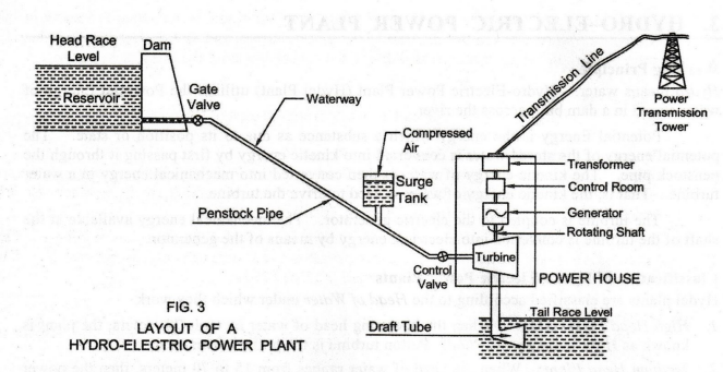
1. LAYOUT OF A HYDRO-ELECTRIC POWER PLANT
Fig.
3 shows the schematic representation of a Hydro-Electric Power Plant. Its
elements are:
1.
Catchment Area
2.
Water Reservoir
3.
Head Race Level:
4.
Dam
5.
Gate Valve
6.
Penstock Pipe
7.
Surge Tank
8.
Waterway
9.
Water Turbine
10.
Draft Tube
11.
Tail Race and Tail Race Level
12.
Power House
1.
Catchment Area
Catchment
Area of a hydro-plant is the whole area behind the dam, draining into a stream
or river across which the dam is built at a suitable location.
2.
Water Reservoir
Continuous
availability of water is the basic necessity for a hydro-electric plant. Whole
of the water collected from catchment area during rainy season is stored in the
reservoir. The main purpose of the reservoir is to store the water during rainy
season and supply the same during dry season. Capacity of the reservoir depends
upon the catchment area and rainfall at that place. The water head available
for power generation depends on the reservoir height.
3.
Head Race Level
Water
surface in the storage reservoir is known as Head Race Level.
4.
Dam
A
Dam is a structure of masonry or some other material built at a suitable
location across the river. The function of a Dam is to increase the height of
water level behind it (called Water Head), which ultimately increases the
reservoir capacity. In order to generate the required quantity of power, it is
necessary that a sufficient water head is available.
Spillway:
Excess accumulation of water endangers the stability of dam construction.
During rainy season, water after a certain safe level in the reservoir
overflows through spillway without allowing an increase in water level in the
reservoir.
5.
Gate Valve
A
Gate Valve is used to regulate or control the flow of water from the dam.
6.
Penstock Pipe
Penstock
Pipe is used to bring water from the dam to the hydraulic turbine. Penstock
pipes are made up of steel or reinforced concrete. The turbine is installed at
a lower level from the dam. Penstock is provided with a Gate Valve at the inlet
and a Control Valve to control the water flow rate into the turbine.
7.
Surge Tank
Water
Hammer: There may be sudden increase of pressure
in the penstock pipe due to sudden backflow of water, as load on the turbine is
reduced. The sudden rise of pressure in the penstock pipe is known as Water
Hammer.
Surge
tank is introduced between the dam and the turbine to reduce the sudden rise of
pressure in the penstock. Otherwise, penstock pipe will be damaged by water
hammer effect.
Surge
Tank
is a small tank into which water flows in or from which water flows out due to
suuden valtations of pressure. sudden variations of pressure.
Surge
tank also serves as a Supply Tank, delivering additional water when the water
in the pipe is accelerated due to the increased load on the turbine and as a
Storage Tank collecting water, when the water is decelerated due to the reduced
load on the turbine.
8.
Waterway
Waterway
through penstock pipe carries water from the dam to Power House.
9.
Water Turbine (Hydraulic Turbine) - Prime Mover
Water
Turbine is also known as Hydraulic Turbine. Water through the penstock pipe
enters into the turbine through the Control Valve. Prime movers which are in
common use are Pelton Turbine, Francis Turbine and Kaplan Turbine. The
potential energy of water entering the turbine is converted into mechanical
energy. The mechanical energy available at the turbine shaft is used to run the
electric generator. The water is then discharged to the river through the Draft
Tube.
10.
Draft Tube
Turbine
outset is connected to the Draft Tube by the Tail Race. Water after doing work
in the turbine passes to the river through the draft tube.
Draft
tube is a metallic pipe or concrete tunnel having gradually increasing
cross-sectional area towards the outlet. Its function is to ensure that little
or no energy is left in water as it discharges into the river.
The
water, after transferring the major part of its energy, enters the draft tube
with remaining kinetic energy. This kinetic energy is quite considerable. All
this energy will be lost, if this water is allowed to discharge freely. So, by
passing the water at the turbine outlet through the draft tube, the velocity is
very much reduced with a corresponding increase in pressure. Therefore, the net
head on the turbine increases and hence the output of the turbine.
11.
Tail Race and Tail Race Level
Tail
Race is a waterway (passage) for discharging the water from the turbine to the
river or canal. The water held in the tail race is called Tail Race Water
Level. Water from the tail race is released for irrigation purposes.
12.
Power House
Power
House accommodates water turbine, generator, control room and transformer. The
function of the step-up transformer is to raise the voltage generated at the
generator terminal before transmitting power to the consumers through
transmission lines.
2. ADVANTAGES OF HYDRO-ELECTRIC POWER PLANT
1.
Renewable Source of Energy: Water is a renewable source of
energy. Water which is the operating fluid, is neither consumed nor converted
into something else.
2.
Cheapest Source of Energy: Water is the cheapest source of
energy, because it exists as a free gift of Nature. The fuels needed for the
thermal, diesel and nuclear plants are exhaustible and expensive.
3.
No Fuel Transportation: No fuel transportation problem
unlike other power stations, since water from rivers and rain is directly
received in the catchment area behind the dam.
4.
No Ash Disposal Problem: There is no ash disposal problem
as in the case of thermal power plant.
5.
No Air Pollution: Hydro-plant does not pose the problem
of air pollution as in the case of thermal plant or radiation hazards as in the
case of nuclear plant.
6.
Variable Loads: Variable loads do not affect the
efficiency in the case of a hydro-plant.
7.
Life of the Plant: Life of hydro-plant is very long (100 –
125 years), compared with thermal plant (30 – 40 years). This is because the
hydro-plants operate at atmospheric temperature, whereas thermal plants operate
at very high temperatures (about 500 to 800°C).
8.
Running Speed: Hydel plant has a low running speed of
300 to 400 rpm. But, the turbines in thermal plant run at a speed of 3000 to
4000 rpm and they require special alloy steel materials and rigid construction.
9.
Additional Benefits: Hydro-plant provides additional
benefits like irrigation, flood control, fishery and serve as a center of
tourist attraction.
10.
Domestic Water Supply: The water storage of hydro-plant
can also be used for domestic water supply
11.
Easy Operation: Hydel plant takes a few minutes to
start and run the plant for power generation. The hydraulic turbines can be put
off and on in a matter of minutes. Thermal power plants and nuclear power
plants lack this facility.
12.
Auxiliaries: Auxiliaries needed for hydro-plant are
less compared to thermal plant of equal capacity. The former requires dam,
penstock pipe, surge tank, water turbine and draft tube. The latter requires
boiler, steam turbine, condenser, cooling tower, L.P. heater, feed pump, H.P.
heater, economizer, air pre-heater and chimney.
13.
Less Staff: Hydel plant requires less supervising
staff.
14.
Low Maintenance Cost: Maintenance cost is low as compared to
thermal plant or nuclear plant of same capacity.
3. DISADVANTAGES OF HYDRO-ELECTRIC POWER PLANT
1.
Transmission Losses: Hydro-plants are situated away from the
load centers. Hence, long transmission lines are required for delivery of
power. This increases the cost of transmission lines and also transmission
losses. But, a thermal plant can be located near the load center, thereby the
transmission cost and transmission losses are considerably reduced.
2.
Failure of Monsoon: The power produced by hydro-plant
depends upon the quantity of water which in turn is dependent upon the
rainfall. The dry year affects the hydro-power generation considerably or power
production may be even stopped due to insufficient water head in the reservoir.
3.
Evaporation Loss: Water in the reservoir is lost due to
evaporation.
4.
High Initial Cost: Initial cost or capital investment of
the plant is high.
5.
Erection of the Plant: Erection of hydro-plant
(construction of dam, etc.) usually takes long period of time.
Basic Civil & Mechanical Engineering: UNIT IV: a. Power plants : Tag: : Working Principle, Classification, Layout Diagram, Advantages, Disadvantages - Hydro-electric power plant
Related Topics
Related Subjects

Basic Civil and Mechanical Engineering
BE3255 2nd Semester 2021 Regulation | 2nd Semester EEE Dept 2021 Regulation