Basic Civil & Mechanical Engineering: UNIT IV: g. Internal combustion engines
Ignition Systems
Classification, Working Principle | Internal combustion engines
In the ignition system, the fuel taken inside the engine cylinder is ignited. According to the method of ignition, internal combustion engines are classified as: 1. Spark Ignition (S.I.) Engines 2. Compression Ignition (C.I.) Engines
IGNITION
SYSTEMS
In
the ignition system, the fuel taken inside the engine cylinder is ignited.
According to the method of ignition, internal combustion engines are classified
as:
1.
Spark Ignition (S.I.) Engines 2. Compression Ignition (C.I.) Engines
1. SPARK IGNITION FOR PETROL ENGINE
In
the petrol engine, ignition takes place by means of an electric spark by a
spark plug at the end of the compression stroke. There are two systems of
ignition for the petrol engine, namely,
Coil or Battery Ignition System and Magneto
Ignition System.
1. Coil or Battery Ignition System
or High Tension System for S.I. Engine
Fig. 14 shows a typical coil ignition circuit
for a four cylinder petrol engine.
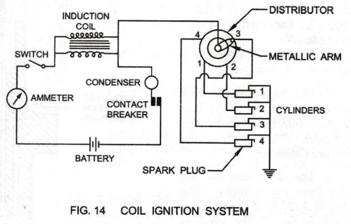
Description
1.
Battery: It provides 12 Volts supply. It is charged by a dynamo driven by engine.
2.
Ammeter: It indicates the primarycurrent in the circuit.
3.
Switch: It is used for putting on and off the primary circuit. It is usually
placed
within the easy reach of the driver.
4.
Induction Coil: It consists of primary winding and secondary winding. The ratio
between the secondary to primary turns is 50 to 1.
5.
Contact Breaker: It is a mechanical device for breaking and making the primary
circuit. . The gap between the two metal points may vary from 0.25 mm to 0.5
mm. 6. Condenser: It is connected across the contact breaker (i) to avoid
sparking at contact breaker points and (ii) to induce a high voltage in the
secondary circuit by causing a more rapid break of the primary current.
Working Principle
When current flows through the primary coil,
it sets up a magnetic field, which surrounds both the primary and secondary
coil. As soon as the primary circuit opens by the contact breaker points,
current from the battery starts charging the condenser.
When
the condenser is fully charged, the flow of current stops and the magnetic
field of the induction coil collapses. This reverses the flow of current, i.e.,
current starts flowing from condenser to battery. Consequently, magnetic field
in the coil is also reversed. This rapid collapse and hence the reversal of
magnetic field in the coil causes very high voltage in the secondary. The high
voltage current is distributed to the spark plug by the metallic arm of the
distributor.
SPARK PLUG (Fig. 15)
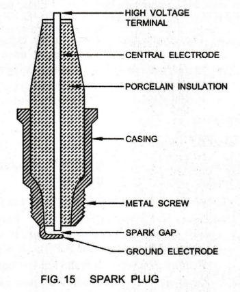
In
the petrol engine, temperature of the air-fuel mixture at the end of
compression stroke is not sufficient to ignite the air-petrol mixture. So, a
spark is provided at the right moment by means of a spark plug.
The
spark plug consists of a metal casing, which is screwed in the combustion
chamber on the cylinder head. A central electrode is insulated with porcelain
or any other ceramic material. It is sealed within the casing as shown. A
ground electrode is fastened to the grounded part of the casing.
At
the end of the compression stroke, the charge is ready for ignition. The
central electrode is provided with high tension supply from the ignition
system. The spark plug transforms the required voltage, generated by the
ignition system into a spark within the combustion chamber.
The
electric spark that is formed, jumps the gap between the ends of two
electrodes. It ignites the air-fuel mixture in the combustion chamber. The
space between the points of the two electrodes is known as Air Gap or Spark
Gap. The gap offers so much resistance to the flow of current that a very high
voltage of 10,000 to 15,000 Volts is required to cause the current to burst
through the gap and produce a spark. The spark gap varies from 0.6 to 1 mm. The
gap should be maintained correctly.
2. Magneto Ignition System
In
this, no battery is required and the magneto acts as its own generator. The
source of electrical energy is the magneto to produce high voltage current.
This current flows to the distributor which connects the spark plug. This is
used for stationary engines.
2 . COMPRESSION IGNITION SYSTEM
In
the diesel engine, no special arrangement is necessary for ignition, since the
temperature of the compressed air is higher than the ignition temperature of
diesel. Diesel is injected into the cylinder shortly before the end of the
compression stroke. As diesel particles come in contact with the hot compressed
air, they vapourise and ignite.
Basic Civil & Mechanical Engineering: UNIT IV: g. Internal combustion engines : Tag: : Classification, Working Principle | Internal combustion engines - Ignition Systems
Related Topics
Related Subjects

Basic Civil and Mechanical Engineering
BE3255 2nd Semester 2021 Regulation | 2nd Semester EEE Dept 2021 Regulation