Basic Civil & Mechanical Engineering: UNIT IV: c. Steam Turbines
Impulse Turbine
Layout Diagram, Working Principle, Construction - Steam Turbines
Impulse is defined as the force exerted on an object when a jet of fluid (liquid or gas) strikes the object with a velocity.
IMPULSE TURBINE
Principle
Refer
Fig. 1. Impulse is defined as the force exerted on an object when a jet of
fluid (liquid or gas) strikes the object with a velocity.
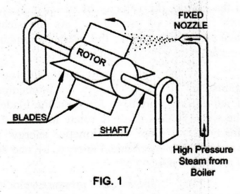
In
an Impulse Turbine, the high pressure high temperature steam from the boiler
expands through a Fixed Nozzle.
The
high velocity jet of steam leaves the nozzle and is made to impact upon the
Blades. The blades are fitted on the periphery of a Rotor. The rotor is mounted
on a shaft. The shaft rotates due to the impulsive force exerted by the steam
jet on the blades.
Description
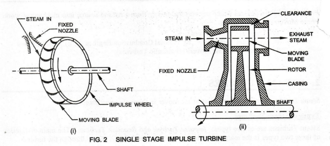
of De Laval Single Stage Impulse Turbine [Figs. 2(i) and (ii) ]
1.
Wheel or Rotor: The wheel or rotor is fitted over a
shaft from which the useful power is available. It is a rotating element of the
turbine on which moving blades are fixed.
2.
Nozzle:
Nozzle (fixed) is a passage for flow of steam where pressure energy is
converted into kinetic energy. Its function is to produce a jet of steam with a
high velocity.
3.
Blades: In this turbine, only one set of moving
blades is rigidly fixed to the rim of the rotor of wheel. It converts the
kinetic energy of steam into mechanical work.
4.
Casing: The casing is the outside cover of the
steam turbine. It is fitted with a fixed nozzle.
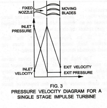
Working
In
the De Laval Single Stage Impulse Turbine, steam is expanded in the fixed
nozzle only. In the nozzle, the velocity of steam increases with decrease of
pressure. As the steam passes over the blades, the pressure remains constant
with a decrease of velocity..
As
the high velocity steam impinges against the blades, it changes the momentum of
jet causing impulsive force on the blades. The wheel is thus made to rotate in
a definite direction. Here, the kinetic energy is converted into mechanical
energy, by one set of moving blades.
Fig.
3 shows the pressure-velocity diagram for the above impulse turbine.
1. COMPOUNDING OF IMPULSE TURBINES
The
disadvantage of De-Laval impulse turbine is its extremely high speed, of the
order of 30,000 rpm. It cannot be employed for practical purposes. To reduce
the high speed, more than one set of blades are used. This is called Compounding
of Impulse Turbine.
In
the compounding method, the steam jet velocity or the steam pressure is
absorbed in stages as it flows over the rotor blades. When steam velocity is
absorbed in stages, it is called Velocity Compounding Impulse Turbine.
When steam pressure is absorbed in stages, it is known as Pressure
Compounding Impulse Turbine.
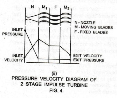
2. VELOCITY COMPOUNDING IMPULSE TURBINE
See
Fig. 4(i). In a Two Stage Velocity Compounding Impulsive Turbine (Curtis
Turbine), moving and fixed blades are placed alternately. Moving blades are
fitted with the wheel. Fixed blade is fitted with casing.
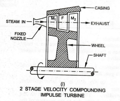
Steam
is expanded in the nozzle from the boiler pressure to condenser pressure, to a
high velocity. It is then passed over the first moving blade M1 . Only
a portion of the high velocity of steam jet is absorbed by this blade. The
remainder is exhausted on to the next fixed or guide . This fixed blade changes
the direction of the steam jet.
The
steam jet is then passed on to the next moving blade M2. A further portion of
steam velocity is absorbed by this second moving blade.
The
process is then repeated as the steam flows over the remaining pairs of blades
until practically all the velocity of the jet has been absorbed and the kinetic
energy is converted into mechanical work.
Note
that all the pressure drop takes place in the nozzle itself. And the pressure
remains constant, as the steam flows over the blades. Hence, the turbine is an
impulse turbine.
Fig.
4(ii) shows the pressure velocity diagram for the two stage velocity
compounding impulse turbine.
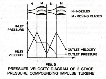
3. PRESSURE COMPOUNDING IMPULSE TURBINE
Fig.
5 shows the Pressure Velocity Diagram of a 2 Stage Pressure Compounding Impulse
Turbine.
In
this type, the expansion of steam takes place in more than one set of nozzles.
Each set of nozzles is followed by a set of moving blades.
The
total pressure drop of the steam does not take place in the first set of
nozzles. But, it is divided up equally between all the sets of nozzles.
Basic Civil & Mechanical Engineering: UNIT IV: c. Steam Turbines : Tag: : Layout Diagram, Working Principle, Construction - Steam Turbines - Impulse Turbine
Related Topics
Related Subjects

Basic Civil and Mechanical Engineering
BE3255 2nd Semester 2021 Regulation | 2nd Semester EEE Dept 2021 Regulation