Basic Civil & Mechanical Engineering: UNIT IV: d. Hydraulic Turbines
Impulse Turbine
Pelton Wheel Hydraulic Turbines - Diagram, Working Principle, Construction
If, at the inlet of the turbine, energy available is only kinetic energy, the turbine is known as Impulse Turbine.
IMPULSE TURBINE
Principle
If,
at the inlet of the turbine, energy available is only kinetic energy, the
turbine is known as Impulse Turbine. In the impulse turbine, all the potential
(pressure) energy of water is converted into kinetic (velocity) energy in the
nozzle before striking the turbine wheel buckets. Hence, an impulse turbine
requires high head and low discharge at the inlet. The water as it flows over the
turbine blades will be at atmospheric pressure. The impulse turbine may be
radial flow or axial flow or tangential flow type.
1. PELTON WHEEL
The
Pelton Wheel is a tangential flow impulse turbine. It is named after L.A.
Pelton, an American Engineer, who developed the first impulse turbine in the
year 1882. See Fig. 1.
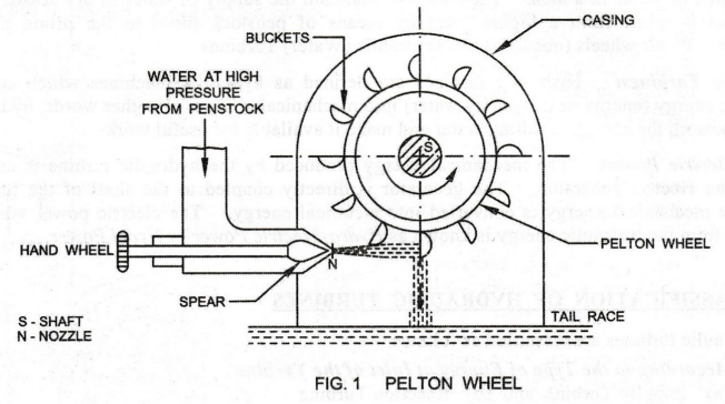
Description
The
main parts of the Pelton Wheel are as follows:
1.
Nozzle and Spear: The amount of water striking the
buckets of the Pelton wheel is controlled by a spear in the nozzle. Spear is a
conical needle operated by a hand wheel.
2.
Pelton Wheel with Buckets: Pelton wheel is a
circular wheel. On the periphery of the wheel, a number of buckets are fixed.
The shape of the buckets is a semi-ellipsoidal cup.
3.
Casing: The function of the casing is to prevent the
splashing of water and to discharge the water to tail race.
Working
Water
at high pressure from the penstock pipe enters the nozzle provided with a
spear. The pressure energy of water is converted into velocity energy, as it
flows through the nozzle. By
The
jet of water at high velocity from the nozzle strikes the buckets at the center
of the cup. The impulsive force of the jet striking on the buckets causes the
rotation of the wheel in the direction of the striking jet. Thus, the pressure
energy of the water is converted into mechanical energy. The pressure inside
the casing is atmospheric.
The
Pelton Wheel operates under a high head of water. Therefore, it requires less
quantity of water. Draft tubes are not usually used with it.
Basic Civil & Mechanical Engineering: UNIT IV: d. Hydraulic Turbines : Tag: : Pelton Wheel Hydraulic Turbines - Diagram, Working Principle, Construction - Impulse Turbine
Related Topics
Related Subjects

Basic Civil and Mechanical Engineering
BE3255 2nd Semester 2021 Regulation | 2nd Semester EEE Dept 2021 Regulation