Electromagnetic Theory: Unit III: (b) Magnetic Forces, Magnetic Materials and Inductance
Inductance - Self Inductance and Mutual Inductance
Statement, Definition, Formula, Circuit Diagram, Solved Example Problems
When two such coils are placed very close to each other, there exists a mutual inductance between the two. In this section, we will discuss the concept to self inductance and mutual inductance.
Inductance - Self Inductance and Mutual Inductance
AU
: May-12, Dec.-04, 12, 14, 16
•
A wire or conductor of certain length, when twisted into coil becomes a basic
inductor. For every conductor carrying current I and producing magnetic field ![]() ,
there exists a self inductance. When two such coils are placed very close to
each other, there exists a mutual inductance between the two. In this section,
we will discuss the concept to self inductance and mutual inductance.
,
there exists a self inductance. When two such coils are placed very close to
each other, there exists a mutual inductance between the two. In this section,
we will discuss the concept to self inductance and mutual inductance.
1. Self Inductance
•
When a closed conducting path or a circuit carries current I, a magnetic field
B is produced. This causes a magnetic flux ϕ which is given by,

In
the circuit or slosed path consists N turns, the flux produced by the magnetic
field ![]() , links with each turn of the circuit. The flux linkage is
defined as the product of number of turns N and the total flux ϕ linking each of the turn. It is denoted by λ
and is measured in weber turn (Wb • t). Hence we can write,
, links with each turn of the circuit. The flux linkage is
defined as the product of number of turns N and the total flux ϕ linking each of the turn. It is denoted by λ
and is measured in weber turn (Wb • t). Hence we can write,
λ
= N . ϕ wb . t ….. (8.10.2)
•
The flux linking with each turn of the circuit is proportional to the current
flowing through the circuit. The flux linkage with the circuit of N turns,
carrying current I is as shown in the Fig. 8.10.1.

•
The ratio of the total flux linkage to the current flowing through the circuit
is called inductance and it is given by,
L
= (N ϕ / I = λ / I ) H ...(8.10.3)
•
The inductance is also known as self-inductance of the circuit as the flux
produced by the current flowing through the circuit links with the same
circuit. The self inductance or inductance is measured in henry (H) which is equivalent
to one weber-turn/ampere (Wb-1 /A).
2. Mutual Inductance
•
Consider that two different circuits with self inductances L1 and L2
are kept close to each other as shown in the Fig. 8.10.2. Let N1
and N2 be the number of turns for the two circuits and let I1 and I2
be the currents through two circuits as shown in the Fig. 8.10.2.

• As two circuits are placed very close to each other, these circuits interact magnetically with each other. The flux produced by circuit 1, due to current I flowing through it, is denoted by 911. Similarly the flux produced by circuit 2, due to the current I2 flowing through it, is denoted by ϕ22. The flux produced by each circuit links with the circuit itself and the other circuit too. The part of flux ϕ11 that links with circuit 2 is denoted by ϕ12. Similarly the part of flux ϕ22 that links with circuit is denoted by ϕ21. The mutual inductance between the two circuits is defined as the flux linkage of to the current in other circuit. Thus the inductance M12 is given by,
M12
= Flux linkage of circuit 1 / Current in circuit 2
=
N1 ϕ21 / I2
….. (8.10.4)
•
Similarly the mutual inductance M21 is given by,
M21
= Flux linkage of circuit 2 / Current in circuit 1
=
N2 ϕ12 / I1
….. (8.10.5)
•
If the medium surrounding two circuits is linear without ferromagnetic
material, then the mutual inductances represented in equations (8.10.4) and
(8.10.5) are equal. Thus for linear medium around two circuits, we can write,
M12
= M21 = M ….. (8.10.6)
•
The mutual inductance between two magnetic circuits depends on the magnetic
interaction existing between the two circuits. Similar to the self inductance,
the mutual inductance is also measured in henry (H) which is equivalent to one
weber-tum per ampere (Wb-1 /A).
3. Coefficient of Coupling between Two Circuits
•
When the two magnetic circuits kept closed to each other interacts with each
other magnetically through the flux linkages in the circuit due to the current
in other circuit then the circuits are called magnetically coupled circuits.
•
Consider an example of the magnetically coupled circuits discussed in section
8.10.2. The self inductances of the circuit 1 and circuit 2 are given by,
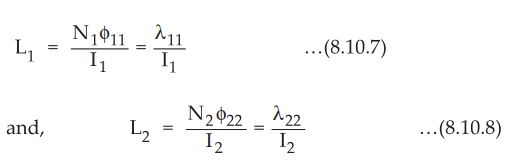
•
The flux linking with circuit 2 due to current in circuit 1 is denoted by ϕ12.
This flux is actually the part of the total flux produced by the current in the
circuit 1. Hence we can write,
ϕ12
= K1 ϕ11 .....(8.10.9)
•
Similarly for the flux ϕ21 which is the part of flux ϕ22 can
be written as,
Φ21
= K2 ϕ22 ...(8.10.10)
•
Rewriting the expressions for the mutual inductances as follows,
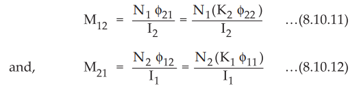
•
Assuming linear medium surrounding two circuits, we can write,
M12
= M21 = M
Hence
we can write,

where
K is called coefficient of coupling between two coils.
Hence
we can write,
K
= M / √L1L2 .....(8.10.14)
4. Inductance of a Solenoid
•
Consider a solenoid of N turns as shown in the Fig. 8.10.3.

•
Let the current flowing through the solenoid be I ampere. Let the length of the
solenoid be I and the cross-sectional area be A.
•
From the results obtained in previous sections, the field intensity inside the
solenoid is given by,
H
= NI / l A/m ...
(8.10.15)
•
The total flux linkage is given by,
Total
flux linkage = N ϕ = N (B) (A) = N (μH) (A)
Total
flux likage = μ NHA = μN[NI / l] A
=
μN2IA / l ...
(8.10.16)
•
Thus the inductance of a solenoid is given by,
L
= Total flux linkage / Total current = μN2IA / l(I)
L
= ( μN2IA / l ) H ….. (8.10.17)
5. Inductance of a Toroid
•
Consider a toroidal ring with N turns and carrying current I. Let the radius of
the toroid be R as shown in the Fig. 8.10.4.

•
The magnetic flux density inside a toroidal ring is given by,
B
= µNI / 2 πR …..
(8.10.18)
•
The total flux linkage of a toroidal ring having N turns is given by,
Total
flux linkage = N ϕ
But
ϕ = (B) (A) where A = Area of cross-section of a toroidal ring
Total flux linkage = N (B) (A)
The
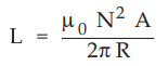
inductance of a toroid is given by,
L
= Total flux linkage / Total current = μN2IA / (2 πR)
(I)
L
= μN2IA / (2 πR) H ….. (8.10.19)
where
A = Area of cross-section of a toroidal ring = πr2 m2
•
For a toroid with N number of turns h as the height of toroid with r1
as inner radius and r2 as outer radius, the inductance is given by
L
= (μN2h / 2 π) ln (r2 / r1 ) H
….. (8.10.20)
6. Inductance of a Co-axial Cable
•
Consider a co-axial cable with inner conductor radius a and outer conductor
radius b as shown in the Fig. 8.10.5. Let the current through the coaxial cable
be I.

• For the co-axial cable the field intensity at any point between inner and outer conductors is given by,
H
= I / 2 πr where
a < r < b ... (8.10.21)
But
B = µH = µI / 2 πr ...
(8.10.22)
•
Now assume that the axis of the cable is along z-axis as shown in Fig. 8.10.5.
The magnetic flux density will be in radial plane extending from r = a to r = b
and z = 0 to z = d.

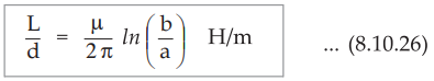
The inductance of a co-axial cable may be expressed per unit length as,
Ex.
8.10.1 Calculate the inductance of a solenoid of 200 turns wound tightly on a
cylindrical tube of 6 cm diameter. The length of the tube is 60 cm and the
solenoid is in air.
Sol.
:
For a given solenoid in air, μ = μ0 = 4л × 10-7 Wb/A.m, N = 200
d
= 6 cm = 6 × 10⁻²m hence
r
= d/2 3 × 10⁻² m, l = 60 cm = 60 × 10−2 m hence
The
inductance of a solenoid is given by,

Ex.
8.10.2 Calculate the inductance of a ring shaped coil of mean diameter 20 cm,
wound on a wooden core of 2 cm diameter containing 200 turns.
AU
: Dec.-16, Marks 8
Sol.
:
Coil diameter = 20 cm,core diameter = 2 cm, µr = 1

Ex.
8.10.3 A solenoid has an inductance of 20 mH. If the length of the solenoid is
increased by two times and the radius is decreased to half of its original
value, find the new inductance.
Sol.
:
The inductance of the solenoid is given by,
L
= μN2A / l = 20 mH
Now
length is made 2l while the radius is made | Then the inductance is
given by,

Ex. 8.10.4 Calculate the self inductance of infinitely long solenoid.
Sol. : For infinitely long solenoid, the magnetic flux density inside the solenoid per unit length is,
B
= µH = µIN / l = µIn ... (1)
Where
n = N / l
=
Number of turns per unit length.
Assume
that A is the cross-sectional area of the solenoid, then the total flux through
the cross-section is,
ϕ
= BA = µInA ... (2)
But
the flux represented by equation (2) is the flux for a unit length of solenoid.
The flux linkage per unit length is,

Ex. 8.10.5 A coil of 500 turns is wound on a closed iron ring of mean radius 10 cm and cross-section area of 3 cm2. Find the self inductance of the winding if the relative permeability of iron is 800.
Sol.
:
For a toroidal ring of iron,

Ex. 8.10.6 An air-core toroid with rectangular cross-section, has 700 turns, with inner radius of 1 cm and outer radius of 2 cm and height is 1.5 cm. Find inductance using 1) The formula for sq. cross section of toroids 2) The approximate formula for general toroid, which assumes a uniform H at mean radius.
Sol.
:
N = 700, h = height = 1.5 cm = 1.5 × 10⁻²m
r1
= Inner radius = 1 cm = 1 × 10⁻²m r2 = Outer radius = 2 cm = 2 × 10⁻²m
1)
In general, inductance of a toroid of square cross section is given by,

=
1.0189 mH
2)
By general approximate formula for toroid, the inductance is given by,
where
A = Area of square cross-section = (1 cm) (1.5 cm) = 1.5 × 10- 4 m2
r
= Mean radius = 1.5 cm = 1.5 × 10- 2 m
L
= 4 × π × 10-7 × (700)2 × (1.5 × 10-4) / 2 × π
× 1.5 × 10-2
=
0.98 mH
Thus
for toroid, with radius larger than the cross-section, the inductance obtained
by both formulae are approximately same.
Ex.
8.10.7 An air core toroid has circular cross section of 4 mm radius. Find the
inductance if there are 2500 turns and the mean radius is 20 mm.
Sol.
:
Mean radius R = 20 mm = 20 × 10-3 m ,
N
= 2500
Radius
of cross-section r = 4 mm = 4× 10⁻³
m,
N
= 2500
For
air, µ r = 1
The
inductance of toroid is given by,

Ex.
8.10.8 The core of a toroid is of 12 cm2 area and is made up of
material with µr = 200. If the mean radius of the toroid is 50 cm,
calculate the number of turns needed to obtain an inductance of 2.5 H.
Sol.
:

Ex.
8.10.9 Find inductance per unit length of a co-axial cable if radius of inner
and outer conductors are 1 mm and 3 mm respectively. Assume relative
permeability unity.
Sol.
:
For a co-axial cable, the inductance per unit length is given by,

Ex.
8.10.10 Calculate the inductance of a 10 m length of co-axial cable filled with
a material for which µr = 80 and radii of inner and outer conductors are 1 mm
and 4 mm respectively.
Sol.
:

Ex.
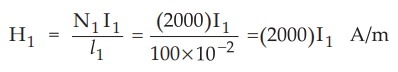
8.10.11 A solenoid with N1 = 2000, r1 = 2 cm and li = 100
cm is concentric within a second coil of N2 = 4000, r2 =
4 cm and l2 = 100 cm. Find mutual inductance assuming free space
conditions.
Sol.
:
For a solenoid with large length as compared to small cross section, the magnetic
field intensity inside the coil can be assumed to be constant and zero for
points just outside the solenoid.
Let
the current flowing through the coil be I1
Then
the magnetic field intensity is given by,
The
magnetic flux density is given by,

Total
flux produced is given by,

The
flux calculated above can only link with the second coil as H1 and B1
are zero outside the coil 1.
The
mutual inductance between two coils is given by,

Ex.
8.10.12 The magnetic circuit of an iron ring with mean radius of 10 cm has a
uniform cross-section of 10-3 m2. The ring is wound with
two coils. If the circuit is energized by a current i1 (t) = 3 sin
100π t A in the first coil with 200 turns, find the induced emf in the second
coil with 100 turns. Assume that µ = 500 µ0.
AU
: Dec.-14, Marks 4
Sol.
: For toroid 1 :

Examples
for Practice
Ex.
8.10.13 Calculate the inductance of a solenoid
of 200 turns wound tightly on a cylindrical tube of 6 cm diameter. The length
of the tube is 60 cm and the solenoid is in air.
[Ans.:
0.2368 mH]
Ex.
8.10.14 An air-core toroid with rectangular
cross-section, has 700 turns, with inner radius of 1 cm and outer radius of 2
cm and height is 1.5 cm. Find inductance using i) The formula for square cross
section of toroids ii) The approximate formula for general toroid, which
assumes a uniform H at mean radius.
[Ans.:
1.0189 mH, 0.98 mH]
Ex.
8.10.15 A solenoid with Ni = 2000, r^ = 2 cm
and Il = 100 cm is concentric within a second coil of N2 = 4000, r2 = 4 cm and
12 = 100 cm. Find mutual inductance assuming free space conditions.
[Ans.:
12.633 mH]
Review Questions
1. Derive the expressions for the inductance of
i) Solenoid ii) Toroid iii) Co-axial cable.
2. Write a note on mutual inductance.
3. Derive expression for inductance of a toroid.
AU : Dec.-04, Marks 10
4. Find self inductance of a solenoid.
Electromagnetic Theory: Unit III: (b) Magnetic Forces, Magnetic Materials and Inductance : Tag: : Statement, Definition, Formula, Circuit Diagram, Solved Example Problems - Inductance - Self Inductance and Mutual Inductance
Related Topics
Related Subjects

Electromagnetic Theory
EE3301 3rd Semester EEE Dept | 2021 Regulation | 3rd Semester EEE Dept 2021 Regulation