Electrical Machines II: UNIT III: a. Three Phase Induction Motor
Induction Generators
Thus when the slip of the induction motor is negative i.e. when the induction motor runs faster than synchronous speed, the induction motor runs as a generator called induction generator.
Induction Generators
To
run the induction machine as a generator, its slip must be less than zero i.e.
negative. The negative slip indicates that the rotor is running at a speed
above the synchronous speed. When running as a generator it takes mechanical
energy and supplies electrical energy from the stator. As the speed of
induction generator is not in synchronism with the line frequency, it is often
called asynchronous generator.
Thus
when the slip of the induction motor is negative i.e. when the induction motor
runs faster than synchronous speed, the induction motor runs as a generator
called induction generator.
In
the Fig. 5.23.1 the induction motor is shown which is driven by a mover like
petrol engine. The motor is supplied with electrical power from 3 phase lines.
When the motor speed exceeds the synchronous speed, the active power is
delivered by the motor and the corresponding mode of operation of motor is
called generating mode.
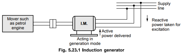
The induction generator is not self exciting
in the sense that supply must be maintained to act is as a generator. Thus it
must be operated with other generators which supplies it exciting current of
fixed frequency which is required for the production of rotating magnetic
field. Thus it takes reactive power from the line to create the magnetic field.
Let
us consider that a 3 phase induction motor is provided with exciting current of
say any frequency f. Due to this a rotating magnetic field of speed 120f / P is
produced.
Now
if the slip is zero, there will not be any e.m.f. or current in the rotor
winding. The stator will take only the magnetizing current from the line.
If
now the speed of the motor is increased above the synchronous speed slightly,
the e.m.f. and current of slip frequency will appear in the rotor winding but
with opposite direction as compared to the direction when it is operating below
the synchronous speed. The slip frequency current in the rotor produces
rotating m.m.f. moving at slip speed relative to the rotor winding but the
direction is reversed compared to when it is acting as motor. The rotor m.m.f.
moves in the air gap at the same speed as that of rotating magnetic field. Thus
relative to the stator the rotor current has line frequency.
The
magnetizing effect of rotor current is balanced by the component of primary
current. Thus there is supply of current from stator winding to line. Thus
independent of value of negative slip, the primary current will have the frequency
that corresponds to speed of rotating magnetic field. The frequency of the
current is same as that of the generator connected to the line.
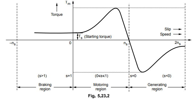
The
torque-slip characteristics for motoring and generating action is shown in the
Fig. 5.23.2.
The
construction of induction generator is same as that of motor with the
difference that the direction of rotation of the motor and a generator is
opposite for the same current direction.
1. Phasor Diagram of Induction Generator
The
action of induction machine as a generator can be explained from the phasor
diagram.
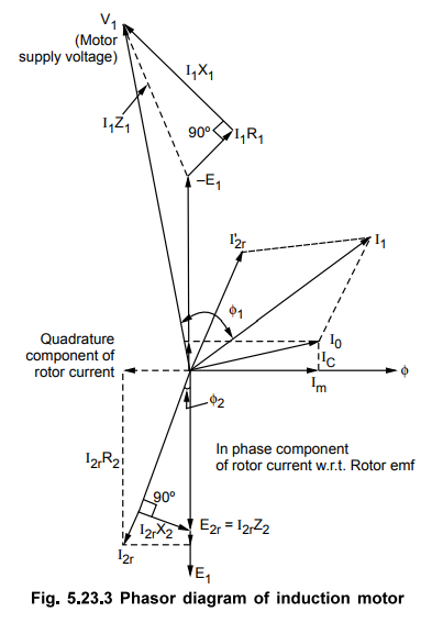
Consider
the phasor diagram of the induction motor on load.
Let
us first consider the speed of the induction machine is less than synchronous
speed so that machine takes current I1 from supply. This current I1is
phasor sum of no load current Io and I2r which is
opposite of I2r and referred as reflected rotor current in stator.
The rotor current can be resolved into two components, one in phase with rotor
emf and the other one is quadrature component.
The
rotor current I2r is given by,
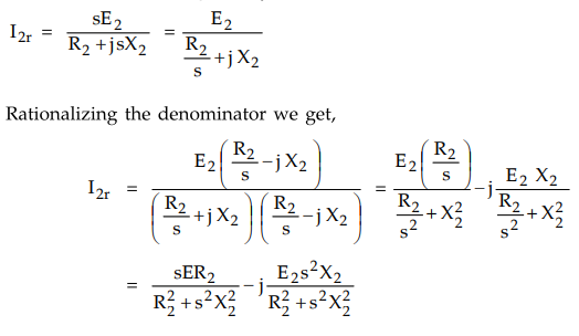
Let
the real part of above current be denoted by A while the imaginary part of the
current be denoted by B. Thus the total rotor current I2r be assumed
as A - jB.
Now
let the speed of the induction machine is increased. With increase in speed of
prime mover i.e. of rotor of induction motor slip goes on reducing and hence
the rotor current also as it depends on it. Thus I2r decreases.
At
synchronous speed, it completely vanishes. Hence its opposite cu rrent I2r
also vanished and the resultant stator current is nothing but the no load
current I0. The core losses are supplied from line whereas friction
and windage losses are supplied mechanically.
When
the speed is increased further the machines enters in generating region. At
zero power factor no power is interchanged between machine and supply lines.
But the machine generates power to meet its core losses. When the speed is
increased, the current I2r increases in magnitude but it changes the
phase. The current supplied by the generator will be then vector sum of Io
and I2r which is reversed in phase as indicated in the phasor
diagram.
The
rotor current is now given by
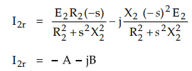
It
can be seen that the in phase component reverses while the quadrature component
remains in the same direction.
The
phasor diagram of induction machine as generator is shown in Fig. 5.23.4.
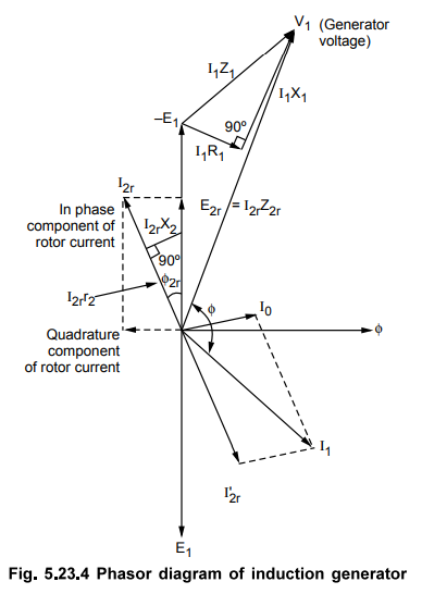
The
current I2r leads the voltage - E2r which is opposite of E2r.
The angle between V1 and I1 is more than 90° which shows
that electric power of the machine is negative i.e. it is supplying the power.
Thus when the rotor is rotated above synchronous speed with the rotating field
remaining in the same direction, then the direction of cutting of rotor is in
opposite direction which results in reversal of rotor emf, current and torque.
The machine is said to be operating in generating mode.
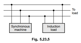
2. Externally Excited Induction Generator
The
induction generator is either self excited type or externally excited requiring
external source for its excitation. In externally excited type, it is always
connected to an a.c. supply. Generally, it is operated in parallel with
synchronous machines which is shown in Fig. 5.23.5.
Consider
an example of a load which requires a lagging current which cannot be supplied
by induction generator alone as it supplies leading current. But this current
requirement is fulfilled with the help of synchronous generators operating in
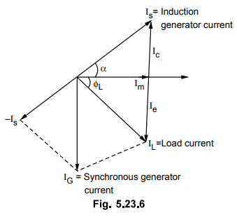
parallel with induction generator. Consider the following phasor diagram.
The
load current IL can be resolved into two components one in phase
component Im and the other quadrature component Ie. The speed of the
induction generator is adjusted in such a way that it supplies current Ic which
is leading one. The induction generator current Is is nothing but vector sum of
Ic and Im.
The
synchronous generator which is in parallel with the induction generator must
supply the remaining part of load current. For this the induction generator
current Is is subtracted vectorially from IL (subtracting vectorially means
reversing Is and adding it with IL). This current (generator current) is
nothing but algebraic sum of currents Ic and Ie. The synchronous generator supplies
no power. The total current supplied by synchronous generator is lagging
quadrature current.
If
the load requires a leading current then theoretically the quadrature component
of current can be supplied entirely by the induction generator. But for satisfactory
operation it should be run in parallel with synchronous generator.
3. Self Excited Induction Generator
If
the bank of delta connected capacitors is operated in parallel with induction
generator then the reactive power requirement of induction generator is met by
capacitors. This arrangement is shown in Fig. 5.23.7.
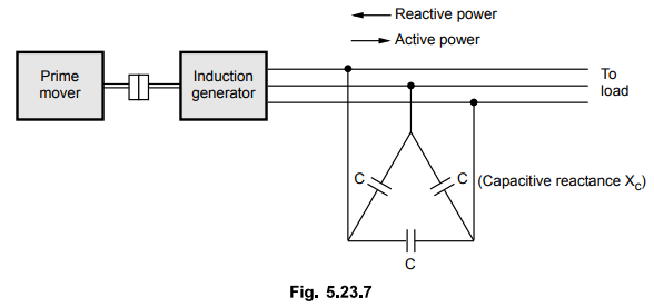
The
induction generator in this case is said to be isolated induction generator
supplying a load. The external voltage source is not required in this case.
Unlike
in synchronous generators, induction generators are not rotating at a definite
speed at a given frequency. The speed varies with load as the load is
proportional to slip. The frequency of the induction generator is same as the
frequency of the line to which it is connected.
In
case of self excited induction generators, the bank of delta connected
capacitors supply the necessary magnetizing current for exciting the generator.
With the load put on the generator, the operating frequency of the stator
changes. It depends on rotor speed and is affected by the load. The voltage is
primarily decided by the capacitor's capacitive reactance at that operating
frequency. The equivalent circuit on per phase basis is as shown in the Fig.
5.23.8
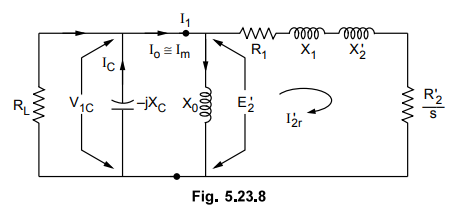
Initially
the induction generator is running at synchronous speed. is the magnetizing
current in motoring mode. If voltage drop in R1 and X1 is neglected then V1 ~ E'2.
But IJH is the magnetising current supplied by capacitors, so it flows through
the capacitors.
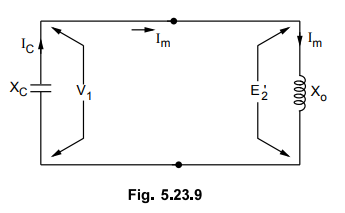
.V1
= Im • Xc
The
simplified equivalent circuit is shown in the Fig. 5.23.9.
The
magnetization characteristics is as shown in the Fig. 5.23.10
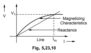
The
intersection of magnetizing characteristics with reactance line gives the no
load voltage. The frequency is rated in this case which changes slightly from
rated with load which in turn changes V1.
4. Circle Diagram of Induction Generator
Using
circle diagram, the induction generators can also be analysed.
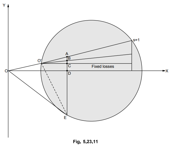
As
the inphase component of current reverses, direction of current Ii also
changes. It will be below horizontal shown by OE. E is the operating point. As seen
from the circle diagram.
AB
= Rotor Cu loss
BC
= Stator Cu loss
CD
= Constant losses
DE
= Generator output BE = Rotor input
The
slip s is given by,
s
= Rotor Cu loss / Rotor input = AB / BE
Similarly
other required quantities can be obtained from the circle diagram.
5. Comparison of Induction Generator and Synchronous Generator
The
distinct features of induction generator compared to synchronous generators are
as follows :
i)
It will not require d.c. excitation.
ii)
It is not self excited but external a.c. supply of fixed frequency is required.
iii)
The frequency of induction generator is decided by the frequency of the
excitation voltage which is supplying current to it.
iv)
Synchronization of generator is not required as no emf is generated until it is
connected to the line.
6. Advantages
The
following are the advantages of induction generator.
i)
Synchronization for induction generator is not required.
ii)
The construction is rugged for rotating parts.
iii)
Unlike in synchronous machines, there is no danger of hunting or drop out of
synchronism for induction generators.
iv)
When it is short circuited, it delivers small power as its excitation quickly
reduces to zero.
v)
Induction generators are more suitable for high speeds.
vi)
With the help of excitation supply and frequency, the voltage and frequency of
induction generator are controlled.
7. Disadvantages
Although
induction generators are having above mentioned advantages, it has following
disadvantages.
i)
It must be run in parallel with the synchronous machine.
ii)
The load is not deciding the power factor of induction generator but the power
factor depends on slip.
8. Applications
Because
of distinct superiority of the synchronous generator, induction generators are
rarely used to supply commercial power.
One
application of induction generator is in railway for braking purposes. When the
train is moving down a gradient, the induction generator rims above
synchronism. As the torque in this region is negative, the braking action is
achieved in the train. In addition to this the energy generated by induction
generator is given to the line so that the load on main generating station is
somewhat relieved. In this case no complicated control apparatus is required.
a.
Importance of Induction Generators in Wind Mill
The
induction generator is extremely important in wind power electricity generation
system. It is suitable because the stator frequency depends on that of the
paralleled synchronous machines and not on the rotor speed.
Induction
generator is most commonly used in wind turbines because of low cost,
ruggedness, operates with slip (synchronism not required), availability in many
sizes and advance technology available.
Induction
generators have outstanding operation as either motor or generator. They have
robust construction features. It provides natural protection against short
circuits. The abrupt changes in speed are easily absorbed by its solid rotor.
Also any surge in the current is damped by the magnetization path of the core,
avoiding the possibility of demagnetization which is possible in case of
permanent magnet generators.
Example
for Practice
Example
5.23.1 A 220 V, 3-phase, 50 Hz, 4-pole induction
machine is running as generator. Stator resistance per phase - 0.545 ohm. At a
particular value of slip, the observed data are as under :
V
- 220 V, stator current 12 AJphase. Output - 3910 watts. Slip speed - 72 rpm.
Constant losses from no load run - 213 watts of which 65 watts represent
friction and windage. Find the efficiency.
[Ans.:
ƞ = 85.65 %]
Review Questions
1. Write a brief note on induction generator.
2. Explain the operation of induction machine as a generator
with neat diagram.
3. Draw and explain circle diagram of an induction generator.
4. State the advantages and disadvantages of an induction
generator.
5. State the applications cf an induction generator.
Electrical Machines II: UNIT III: a. Three Phase Induction Motor : Tag: Engineering Electrical Machines - II : - Induction Generators
Related Topics
Related Subjects

Electrical Machines II
EE3405 Machine 2 EM 2 4th Semester EEE Dept | 2021 Regulation | 4th Semester EEE Dept 2021 Regulation