Electrical Machines II: UNIT III: a. Three Phase Induction Motor
Induction Motor as a Transformer
The normal transformer has no air gap as against this an induction motor has distinct air gap between its stator and rotor.
Induction Motor as a Transformer
We
know that, transformer is a device in which two windings are magnetically
coupled and when one winding is excited by a.c. supply of certain frequency,
the e.m.f. gets induced in the second winding having same frequency as that of
supply given to the first winding. The winding to which supply is given is
called primary winding while winding in which e.m.f. gets induced is called
secondary winding. The induction motor can be regarded as the transformer.
The
difference is that the normal transformer is an alternating flux transformer
while induction motor is rotating flux transformer. The normal transformer has
no air gap as against this an induction motor has distinct air gap between its
stator and rotor.
In
an alternating flux transformer the frequency of induced e.m.f. and current in
primary and secondary is always same. However in the induction motor frequency
of e.m.f. and current on the stator side remains same but frequency of rotor
e.m.f. and current depends on the slip and slip depends on load on the motor.
So we have a variable frequency on the rotor side. But it is important to
remember that at start when N = 0 the value of slip is unity (s = 1), then
frequency of supply to the stator and of induced e.m.f. in the rotor is same.
The effect of slip on the rotor parameters is already discussed in the previous
section.
And
last difference is that in case of the alternating flux transformer the entire
energy present in its secondary circuit, is in the electrical form. As against
this, in an induction motor part of its energy in the rotor circuit is in
electrical form and the remaining part is converted into mechanical form.
In
general, an induction motor can be treated as a generalized transformer as
shown in the Fig. 5.8.1. In this, the slip ring induction motor with star
connected stator and rotor is shown.

So
if E1= Stator e.m.f. per phase
in volts.
E2
= Rotor induced e.m.f. per phase in volts at start when motor is at standstill.
Then
according to general transformer there exists a fixed relation between E1
and E2 called transformation ratio.
At
start when N = 0, s = 1
and
we get, 
Key Point So if stator
supply voltage is known and ratio of stator to rotor turns per phase is known
then the rotor induced e.m.f on standstill can be obtained.
Example
5.8.1 For a 4 pole, 3 phase, 50 Hz induction
motor ratio of stator to rotor turns is 2. On a certain load, its speed is
observed to be 1455 r.p.m. when connected to 415 V supply. Calculate,
i)
Frequency of rotor e.m.f. in running condition
ii)
Magnitude of induced e.m.f. in the rotor at standstill
iii)
Magnitude of induced e.m.f. in the rotor under running condition.
Assume
star connected stator.
Solution
:
The given values are, K = rotor tums/stator turns = 1/2 = 0.5 and
P
= 4, f = 50 Hz, N = 1455 r.p.m., E1line = 415 V

ii)
At standstill, induction motor acts as a transformer so,
E
2ph / E 1ph = Rotor
turns / Stator turns = K
But
ratio of stator to rotor turns is given as 2, i.e.
N1
/ N2 = 2
N2
/ N1 = ½ = K
and E1 line = 415 V
The
given values are always line values unless and until specifically stated as per
phase.

iii)
In running condition,
E2r
= s E2 = 0.03 × 119.8 = 3.594 V
The
value of rotor induced e.m.f. in the running condition is also very very small.
Example
5.8.2 A 3-phase induction motor with star connected
rotor has induced electromotive force of 60 V between slip rings at standstill
on open circuit with normal voltage applied to the stator. The resistance and
standstill leakage reactance of each rotor phase are 0.6 Ω and 4 Ω
respectively. Calculate the current per phase in the rotor :
i)
When it is at standstill and connected to a resistance of 5 Ω and reactance of
2 Ω per phase and
ii)
When running with a slip of 4 % with its rotor terminals short circuited.
Solution
:
The e.m.f. between the slip rings = E2 = 60 V, R2 = 0.6 Ω,
X2 = 4 Ω
i)
Rotor standstill and Rx = 5 Ω, Xx = 2 Ω added
externally.
The
equivalent circuit is shown in the Fig. 5.8.2.

This
is rotor current per phase.
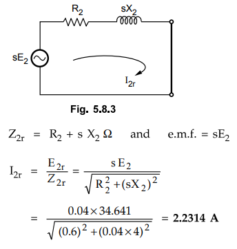
ii)
s = 4 % i.e. 0.04 and rotor terminals shorted.
Rotor
terminals shorted means external resistance and reactance completely removed.
Rx
= Xx = 0 Ω
This is shown in the Fig. 5.8.3.
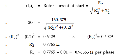
Example
5.8.3 A 1000 V, 50 Hz, 3 phase slip ring induction
motor has star connected stator. The ratio of stator to rotor turns is 3.6. The
rotor standstill impedance is 0.01 + j 0.2 Ω. Calculate the external resistance
per phase required in rotor circuit to limit starting rotor current to 200 A.
Solution
:
The given values are,

Let
at start Rx be the external resistance per phase, introduced in
rotor circuit.
R’2
= R2 + Rx ...
At start
Example
for Practice
Example
5.8.4 A 3 phase, 4 pole, 50 Hz, induction motor has
slip ring rotor. The rotor winding is star connected with 0.2 Q of resistance
per phase and standstill reactance of 1 Q per phase. Its open circuit e.mf.
between the slip rings is 120 V, when stator is excited by a rated voltage. Its
full load speed is 1440 r.p.m. Find the rotor current and rotor power factor.
i)
At start and ii) On full load condition.
[Ans.:
67.93 A per phase, 13.586 A]
Review Question
1. Induction motor is a generalised transformer. "Justify
the statement.
Electrical Machines II: UNIT III: a. Three Phase Induction Motor : Tag: Engineering Electrical Machines - II : - Induction Motor as a Transformer
Related Topics
Related Subjects

Electrical Machines II
EE3405 Machine 2 EM 2 4th Semester EEE Dept | 2021 Regulation | 4th Semester EEE Dept 2021 Regulation