Electron Devices and Circuits: Unit V: (a) Feedback Amplifiers
Input and Output Resistance
Feedback Amplifiers
• If the feedback signal is added to the input in series with the applied voltage (regardless of whether the feedback is obtained by sampling the output current or voltage), it increases the input resistance.
Input and Output Resistance
1. Input resistance
• If the feedback signal is added to the input in series with the applied voltage (regardless of whether the feedback is obtained by sampling the output current or voltage), it increases the input resistance.
•
Since the feedback voltage Vf opposes Vs, the input current I; is less than it
would be if Vf were absent, as shown in the Fig. 9.9.1
•
Hence, the input resistance with feedback Rif = Vs / Ii is greater than the
input resistance without feedback, for the circuit shown in Fig. 9.9.1.

•
On the other hand, if the feedback signal is added to the input in shunt with
the applied voltage (regardless of whether the feedback is obtained by sampling
the output voltage or current), it decreases the input resistance.
•
Since Is = Ii + If, the current Is drawn from the signal source is increased
over what it would be if there were no feedback current, as shown in the Fig.
9.9.2.

•
Hence, the input resistance with feedback
is
decreased for the circuit shown in Fig. 9.9.2. Now we see the effect of
negative feedback on input resistance in different topologies (ways) of
introducing negative feedback and obtain R^ quantitatively.
Ex.
9.9.1 Derive the expression for input resistance for a voltage series feedback.
Sol.
: Step 1 : Draw the equivalent circuit for voltage series amplifier.
•
The voltage series feedback topology shown in Fig. 9.9.3 with amplifier is
replaced by Thevenin's model. Here, Av represents the open-circuit voltage gain
taking Rs into account.
•
Since throughout the discussion of feedback amplifiers we will consider Rs to
be part of the amplifier and we will drop the subscript on the transfer gain
and input resistance (Av instead of Avs and Rif instead
of Rifs)

•
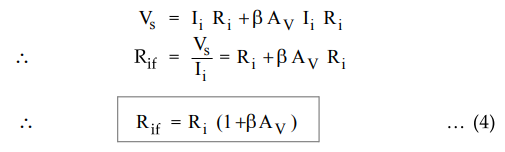
Look at Fig. 9.9.3 the input resistance with feedback is given as
Rif
= Vs / Ii … (1)
Step
2 : Obtain expression for Vs .
Applying
KVL to the input side we get,

Step
3 : Obtain expression for Vo in terms of Ii.
The
output voltage Io is given as

Important
Concept
Av
represents the open circuit voltage gain without feedback and AV is
the voltage gain without feedback taking the load RL into account.
Step
4 : Obtain expression for Rif.
Substituting
value of Vo from equation (3) in equation (2) we get,
Ex.
9.9.2 Derive the expression for input resistance for a current series.
Sol.
: Step 1 : Draw the equivalent circuit for current series feedback amplifier.
•
The current series feedback topology is shown in Fig. 9.9.4 with amplifier
input circuit is represented by Thevenin's equivalent circuit and output
circuit by Norton's equivalent circuit.
•
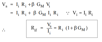
Looking at Fig. 9.9.4 the input resistance with feedback is given as
Rif
= Vs / Ii

Step
2 : Obtain expression for Vs .
Applying
KVL to the input side we get,

Step
3 : Obtain expression for Io in terms of Vi.
The
output voltage Io is given as

Important
Concept
Gm
represents the open circuit voltage gain without feedback and GM is
the voltage gain without feedback taking the load RL into account.
Step
4 : Obtain expression for Rif.
Substituting
value of Io from equation (2) in equation (1) we get,
Ex.
9.9.3 Derive the expression for input resistance for a current shunt feedback.
Sol. : Step 1 : Draw the equivalent circuit
current shunt amplifier.
The
current shunt feedback topology is shown in Fig. 9.9.5 with amplifier input and
output circuit replaced by Norton's equivalent circuit.

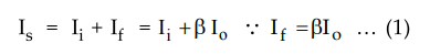
Step
2 : Obtain expression for ls.
Applying
KCL at input node we get,
Step
3 : Obtain expression for Vo in terms of Ii
The
output current I is given as

Important
Concept
Ai
represents the open circuit current gain without feedback and AI
is the current gain without feedback taking the load RL into
account.
Step
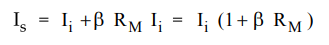
4 : Obtain expression for Rif.
Substituting
value of Io from equation (2) into equation (1) we get,

The
input resistance with feedback is given as

Ex.
9.9.4 Derive the expression for input resistance for a voltage shunt feedback
amplifier.
Sol.
: Step 1 : Draw the equivalent circuit current shunt amplifier.
The
voltage shunt feedback topology is shown in Fig. 9.9.6 with amplifier input
circuit is represented by Norton's equivalent circuit and output circuit
represented by Thevenin's equivalent.

Step
2 : Obtain expression for ls.
Applying
KCL at input node we get,

Step
3 : Obtain expression for Vo in terms of Ii
The
output current I is given as

Important
Concept
Rm
represents the open circuit transresistance without feedback and RM
is the transresistance without feedback taking the load RL into
account
Step
4 : Obtain expression for Rif .
Substituting
value of VQ from equation (2) into equation (1) we get,
The
input resistance with feedback Rif is given as

2. Output Resistance
•
The negative feedback which samples the output voltage, regardless of how this
output signal is returned to the input, tends to decrease the output
resistance, as shown in the Fig. 9.9.7.

•
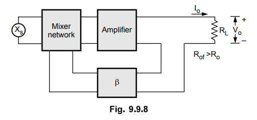
On the other hand, the negative feedback which samples the output current,
regardless of how this output signal is returned to the input, tends to
increase the output resistance, as shown in the Fig. 9.9.8.
•
Now, we see the effect of negative feedback on output resistance in different
topologies (ways) of introducing negative feedback and obtain Rof
quantitatively.
Ex.
9.9.5 Derive the expression for output resistance for a voltage series feedback
amplifier.
AU
: Dec.-16
Sol.
: Step 1 : Draw the equivalent circuit.
In
this topology, the output resistance can be measured by shorting the input
source Vg = 0 and
looking
into the output terminals with RL disconnected, as shown in the Fig. 9.9.9

Step
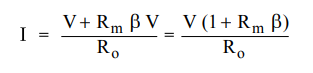
2 : Obtain expression for I in terms of V.
Applying
KVL to the output side we get,

Substitutin
the Vi from equation (2) min quation (1) we get,

Step
3 : Obtain expression for Rof.
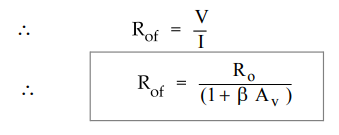
Important
Concept
Here
Av is the open loop voltage gain without taking RL in
account.
Step
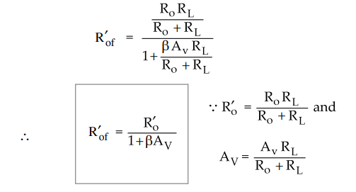
4 : Obtain expression for R’of
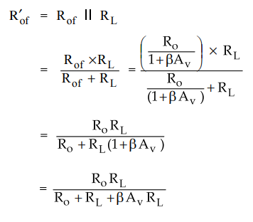
•
Dividing numerator and denominator by (Ro + RL) we get,

Important
Concept
Here
AV is the open loop voltage gain taking RL into account.
Ex.
9.9.6 Derive the expression for output resistance for a voltage shunt feedback
amplifier.
AU
: ECE : May-07
Sol.
: Step 1 : Draw equivalent circuit.
In
this topology, the output resistance can be measured by making Is = 0 and
looking into the output terminals with RL disconnected, as shown in the Fig.
9.9.10.

Step
2 : Obtain expression for I in terms of V.
Applying
KVL to the output side we get,
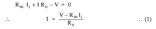
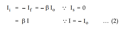
The
input current is given as
Ii
= -If - = - β V. …. (2)
Substituting
Ii from equation (2) in equation (1) we get,
Step
3 : Obtain expression for Rof

Important
Concept
Here,
Rm is the open loop transresistance without taking RL in
account.
Step
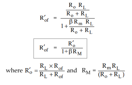
4 : Obtain expression for Rof

Dividing
numerator and denominator by (Ro + RL) we get,
Important
Concept
Here
AV
is the open loop voltage gain taking RL
into account.
Ex.
9.9.6 Derive the expression for output resistance for a voltage shunt feedback
amplifier.
AU
: ECE : May-07
Sol.
: Step 1 : Draw equivalent circuit.
•
In this topology, the output resistance can be measured by making Ig = 0 and
looking into the output terminals with RL disconnected, as shown in the Fig.
9.9.10.

Step
2 : Obtain expression for I in terms of V.
Applying
KVL to the output side we get,

Important
Concept
Here,
RM is the open loop transresistance taking RL in account.
Step
4 : Obtain expression for Rof

Dividing
numerator and denominator by (Ro + RL) we get,
Important
Concept
Here, AM is the open loop transresistance taking RL into account.
Ex. 9.9.7 Derive the expression for output resistance for a current shunt feedback amplifier.
Sol.
: Step 1 : Draw the equivalent circuit
•
In this topology, the output resistance can be measured by open circuiting the
input source Is = 0 and looking into the output terminals, with RL
disconnected, as shown in the Fig. 9.9.11

Step
2 : Obtain expression for I in terms of V
Applying
the KCL to the output node we get,

The
input current is given as
Substituting
value of Ii from equation (2) in equation (1) we get,

Step
3 : Obtain expression for Rof

Important
Concept
Here,
Ai is the open loop current gain without taking RL in
account.
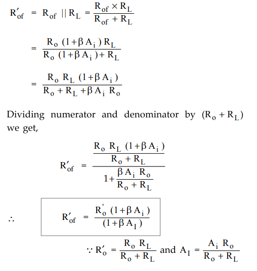
Here, Ai is the open loop tcurrent gain taking RL in account.
Ex.
9.9.8 Derive the expression for output resistance for a current series feedback
amplifier.
Sol.
: Step 1 : Draw the equivalent circuit
•
In this topology the output resistance can be measured by shorting the input
source Vs = 0 and looking
into the output terminals with RL disconnected, as shown in the Fig.
9.9.12.
Step
2 : Obtain expression for I in terms of V.
Applying
KCL to the output node we get,

Important
Concept
Here,
Gm is the open loop transconductance without taking RL in
account.
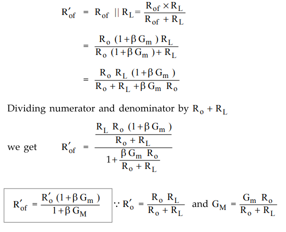
Important
Concept
Note
that here, GM is the open loop current gain taking RL in
account.
Review Questions
1. Obtain the expression for output resistance for all four
topologies.
AU : ECE : May-09, Marks 8
2. Derive the input impedance of a voltage series and current
shunt.
AU : ECE : May-05, 06, Marks 8
3.Draw a block diagram of voltage shunt feedback amplifier and
give its input resistance.
AU : ECE : May-07, Marks 2
4.Draw the block diagram of current series feedback and derive
the expression for Ry
5. Mention the effect
of negative feedback amplifier performance such as :
1) Gain 2) Input and output impedance 3) Sensitivity 4)
Bandwidth.
Also explain the significance of the term (1 + XP) on the above
performance parameters.
6. With a neat block diagram, explain the operation of following
feedback amplifiers :
i) Voltage series feedback amplifiers ii) Current shunt feedback
amplifier.
AU : May-17, Marks 13
Electron Devices and Circuits: Unit V: (a) Feedback Amplifiers : Tag: : Feedback Amplifiers - Input and Output Resistance
Related Topics
Related Subjects

Electron Devices and Circuits
EC3301 3rd Semester EEE Dept | 2021 Regulation | 3rd Semester EEE Dept 2021 Regulation