Microprocessors and Microcontrollers: Unit II: (a) 8085 Instruction Set and ALP
Instruction Set of 8085
Questions : 1. Explain the operations carried out when 8085 executes the instructions, i) MOV A, M ii) XCHG Ui) DAD B iv) DAA 2. How are the 8085 instructions classified according to the functional categories ? 3. What is stack ? And what is the function of stack pointer? 4. Describe with a suitable example the operation of stack. 5. Explain the logical instructions with examples.
Instruction Set of 8085
AU : May-10,11,13,18, Dec.-07,09,ll,12,13,16,17, June-07,11,12, Dec.-04,12,14,16,19
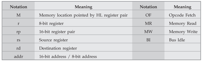
In this section, the instructions from all groups are explained with the help of examples. Before to discuss these instructions, let us get familiar with the notations used in the explanation of instructions. These are :
1. Data Transfer Group
MVI r, data (8) operation : r ← 8-bit data (byte) Bytes : 2
Description : This instruction directly loads a specified register with an 8-bit data given within the instruction. The register r is an 8-bit general purpose register such as A, B, C, D, E, H and L.
Example : MVI B, 60H ; This instruction will load 60H directly into the B register
Addressing Mode : Immediate : Flags Affected : None
Machine Cycles : OF, MR
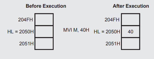
MVI M, data (8) Operation : M ← byte or (HL) ← byte Bytes : 2
Description : This instruction directly loads an 8-bit data given within the instruction into a memory location. The memory location is specified by the contents of HL register pair.
Example : H = 20H and L = 50H
MVI M, 40H ; This instruction will load 40H into memory whose address is 2050H.
Addressing Mode : Immediate and Indirect - Flags Affected : None
Machine Cycles : OF, MR, MW
MOV rd, rs Operation : rd ← rs Bytes : 1
Description : This instruction copies data from the source register into destination register. The rs and rd are general purpose registers such as A, B, C, D, E, H and L. The contents of the source register remain unchanged after execution of the instruction.
Example : A = 20H
MOV B, A ; This instruction will copy the contents of register A (20H) into register B.
Addressing Mode : Register - Flags Affected : None
Machine Cycles : OF, MR, MW
MOV rd, rs Operation : rd ← rs Bytes : 1
Description : This instruction copies data from the source register into memory location pointed by the HL register pair. The rs is an 8-bit general purpose register such as A, B, C, D, E, H and L.
Example : If HL = 2050H, B = 30H.
MOV M, B ; This instruction will copy the contents of B register (30H) into the memory location whose address is specified by HL (2050H).
Addressing Mode : Indirect - Flags Affected : None
Machine Cycles : OF, MW
MOV rd, M Operation : rd ← (HL) Bytes : 1
Description : This instruction copies data from memory location whose address is specified by HL register pair into destination register. The contents of the memory location remain unchanged. The rd is an 8-bit general purpose register such as A, B, C, D, E, H and L.
Example : HL = 2050H, contents at 2050H memory location = 40H
MOV C, M; This instruction will copy the contents of memory location pointed by HL register pair (40H) into the C register.
Addressing Mode : Indirect -Flags Affected : None
Machine Cycles : OF, MR
LXI rp, data (16) Operation : rp ← data (16) Bytes : 3
Description : This instruction loads immediate 16 bit data specified within the instruction into register pair or stack pointer. The rp is 16-bit register pair such as BC, DE, HL or 16-bit stack pointer.
Example : LXI B, 1020H; This instruction will load 10H into B register and 20H into C register.
Addressing Mode : Immediate Flags Affected : None
Machine Cycles : OF, MR, MR
STA addr Operation : (addr) ← A Bytes : 3
Description : This instruction stores the contents of A register into the memory location whose address is directly specified within the instruction. The contents of A register remain unchanged.
Example : A = 50H
STA 2000H ; This instruction will store the contents of A register (50H) to memory location 2000H.
Addressing Mode : Direct Flags Affected : None
Machine Cycles : OF, MR, MR, MW
LDA addr Operation : A ← (addr) Bytes : 3
Description : This instruction copies the contents of the memory location whose address is given within the instruction into the accumulator. The contents of the memory location remain unchanged.
Example : (2000H) = 30H
LDA 2000H ; This instruction will copy the contents of memory location 2000H i.e. data 30H into the A register.
Addressing Mode : Direct Flags Affected : None
Machine Cycles : OF, MR, MR, MR
SHLD addr Operation : (addr) ← L and (addr + 1) ← H Bytes : 3
Description : This instruction stores the contents of L register in the memory location given within the instruction and contents of H register at address next to it. This instruction is used to store the contents of H and L registers directly into the memory. The contents of the H and L registers remain unchanged.
Example : H = 30H, L = 60H
SHLD 2500H ; This instruction will copy the contents of L register at address 2500H and the contents of H register at address 2501H.
Addressing Mode : Direct Flags Affected : None
Machine Cycles : OF, MR, MR, MW, MW
LHLD addr Operation : L ← (addr), H ← (addr + 1) Bytes : 3
Description : This instruction copies the contents of the memory location given within the instruction into the L register and the contents of the next memory location into the H register.
Example : (2500H) = 30H, (2501H) = 60H
LHLD 2500H ; This instruction will copy the contents of memory location 2500H i.e. data SOH into the L register and the contents at memory location 2501H i.e. data 60H into the H register.
Addressing Mode : Direct Flags Affected : None
Machine Cycles : OF, MR, MR, MR, MR
STAX rp Operation : (rp) ← A Bytes : 1
Description : This instruction copies the contents of accumulator into the memory location whose address is specified by the specified register pair. The rp is BC or DE register pair. This register pair is used as a memory pointer. The contents of the accumulator remain unchanged.
Example : BC = 1020H, A = 50H
STAX B ; This instruction will copy the contents of A register (50H) to the memory location specified by BC register pair (1020H).
Addressing Mode : Indirect Flags Affected : None
Machine Cycles : OF, MW
LDAX rp Operation : A ← (rp) Bytes : 1
Description : This instruction copies the contents of memory location whose address is specified by the register pair into the accumulator. The rp is BC or DE register pair. The register pair is used as a memory pointer.
Example : DE = 2030H, (2030H) = 80H
LDAX D ; This instruction will copy the contents of memory location specified by DE register pair (80H) into the accumulator.
Addressing Mode : Indirect Flags Affected : None
Machine Cycles : OF, MR
XCHG Operation : H ↔ D and L ↔ E Bytes : 1
Description : This instruction exchanges the contents of the register H with that of D and of L with that of E.
Example : DE = 2040H, HL = 7080H
XCHG ; This instruction will load the data into registers as follows H = 20H, L = 40H, D = 70H and E = 80
Addressing Mode : Register Flags Affected : None
Machine Cycles : OF
2. Arithmetic Group
ADD r Operation : A ← A + r Bytes : 1
Description : This instruction adds the contents of the specified register to the contents of accumulator and stores result in the accumulator. The r is 8-bit general purpose register such as A, B, C, D, E, H and L.
Example : A = 20H, C = 30H.
ADD C ; This instruction will add the contents of C register, i.e. data 30H to the contents of accumulator, i.e. data 20H and it will store the result 50H in the accumulator.
Addressing Mode : Register Flags Affected : All
Machine Cycles : OF
ADD M Operation : A ← A + (HL) Bytes : 1
Description : This instruction adds the contents of the memory location pointed by HL register pair to the contents of accumulator and stores result in the accumulator. The HL register pair is used as a memory pointer. This instruction affects all flags.
Example : A = 20H, HL = 2050H, (2050H) = 10H
ADD M ; This instruction will add the contents of memory location pointed by HL register pair, 2050H i.e. data 10H to the contents of accumulator i.e. data 20H and it will store the result, 30H in the accumulator.
Addressing Mode : Register Indirect Flags Affected : All
Machine Cycles : OF, MR
ADI data (8) Operation : A ← A + data (8) Bytes : 2
Description : This instruction adds the 8 bit data given within the instruction to the contents of accumulator and stores the result in the accumulator.
Example : A = 50H
ADI 70H ; This instruction will add 70H to the contents of the accumulator (50H) and it will store the result in the accumulator (COH).
Addressing Mode : Immediate Flags Affected : All
Machine Cycles : OF, MR
ADC r Operation : A ← A + r + CY Bytes : 1
Description : This instruction adds the contents of specified register to the contents of accumulator with carry. This means, if the carry flag is set by some previous operation, it adds 1 and the contents of the specified register to the contents of accumulator, else it adds the contents of the specified register only. The r is 8-bit general purpose register such as A, B, C, D, E, H and L.
Example : Carry flag = 1, A = 50H, C = 20H
ADC C ; This instruction will add the contents of C (20H) register to the contents of accumulator (50H) with carry (1) and it will store result, 71H (50H + 20H + 1 = 71H) in the accumulator.
Addressing Mode : Register Flags Affected : All
Machine Cycles : OF
ADC M Operation : A ← A + M + CY Bytes : 1
Description : This instruction adds the contents of memory location pointed by HL register pair to the contents of accumulator with carry and stores the result in the accumulator. HL register pair is used as a memory pointer.
Example : Carry flag = 1, HL = 2050H, A = 20H, (2050H) = 30H.
ADC M ; This instruction will add the contents of memory location pointed by HL register pair, 2050H, i.e. data 30H to the contents of accumulator, i.e. data 20H with carry flag (1). It will store the result (30+20+l=51H) in the accumulator.
Addressing Mode : Register Indirect Flags Affected : All
Machine Cycles : OF, MR
ACI data (8) Operation : A ← A + data (8) + CY Bytes : 2
Description : This instruction adds 8 bit data given within the instruction to the contents of accumulator with carry and stores result in the accumulator.
Example : A = 30H, Carry flag = 1
ACI 20H ; This instruction will add 20H to the contents of accumulator, i.e. data 30H with carry (1) and stores the result, 51H (30 + 20 + 1 = 51H) in the accumulator.
Addressing Mode : Immediate Flags Affected : All
Machine Cycles : OF, MR
DAD rp Operation : HL ← HL + rp Bytes : 1
Description : This instruction adds the contents of the specified register pair to the contents of the HL register pair and stores the result in the HL register pair. The rp is 16-bit register pair such as BC, DE, HL or stack pointer. Only higher order register is to be specified for register pair within the instruction.
Example : DE = 1020H, HL = 2050H
DAD D ; This instruction will add the contents of DE register pair, 1020H to the contents of HL register pair, 2050H. It will store the result, 3070H in the HL register pair.
Addressing Mode : Register Flags Affected : CY
Machine Cycles : OF, BI, BI
SUB r Operation : A ← A - r Bytes : 1
Description : This instruction subtracts the contents of the specified register from the contents of the accumulator and stores the result in the accumulator. The register r is 8-bit general purpose register such as A, B, C, D, E, H and L.
Example : A = 50H, B = 30H.
SUB B ; This instruction will subtract the contents of B register (30H) from the contents of accumulator (50H) and stores the result (20H) in the accumulator.
Addressing Mode : Register Flags Affected : All
Machine Cycles : OF
SUB M Operation : A ← A – M Bytes : 1
Description : This instruction subtracts the contents of the memory location pointed by HL register pair from the contents of accumulator and stores the result in the accumulator. The HL register pair is used as a memory pointer.
Example : HL = 1020H, A = 50H, (1020H) = 10H
SUB M ; This instruction will subtract the contents of memory location pointed by HL register pair, 1020H, i.e. data 10H from the contents accumulator, i.e. data 50H and stores the result (40H) in accumulator.
Addressing Mode : Register Indirect Flags Affected : All
Machine Cycles : OF, MR
SUI data (8) Operation : A ← A - data (8) Bytes : 2
Description : This instruction subtracts an 8 bit data given within the instruction from the contents of the accumulator and stores the result in the accumulator.
Example : A = 40H,
SUI 20H ; This instruction will subtract 20H from the contents of accumulator (40H). It will store the result (20H) in the accumulator.
Addressing Mode : Immediate Flags Affected : All
Machine Cycles : OF, MR
SBB r Operation : A ← A - r - CY Bytes : 1
Description : This instruction subtracts the specified register contents and borrow flag from the accumulator contents. This means, if the carry flag (borrow for subtraction) is set by some previous operation, it subtracts 1 and the contents of the specified register from the contents of accumulator, else it subtracts the contents of the specified register only. The register r is 8-bit register such as A, B, C, D, E, H and L.
Example : Carry flag = 1, C = 20H, A = 40H
SBB C ; This instruction will subtract the contents of C register (20H) and carry flag (1) from the contents of accumulator (40H). It will store the result (40H - 20H - 1 = 1FH) in the accumulator.
Addressing Mode : Register Flags Affected : All
Machine Cycles : OF
SBB M Operation : A ← A - M - CY Bytes : 1
Description : This instruction subtracts the contents of memory location pointed by HL register pair from the contents of accumulator and borrow flag and stores the result in the accumulator.
Example : Carry flag = 1, HL = 2050H, A = 50H, (2050H) = 10H.
SBB M ; This instruction will subtract the contents of memory location; pointed by HL register pair, 2050H, i.e. data 10H and borrow (Carry flag=l) from the contents of accumulator (50H) and stores the result 3FH in the accumulator (50 - 10 - 1 = 3F).
Addressing Mode : Register Indirect Flags Affected : All
Machine Cycles : OF, MR
SBI data (8) Operation : A ← A - data(8) - CY Bytes : 2
Description : This instruction subtracts 8 bit data given within the instruction and borrow flag from the contents of accumulator and stores the result in the accumulator.
Example : Carry flag = 1, A = 50H
SBI 20H ; This instruction will subtract 20H and the carry flag (1) from the contents of the accumulator (50H). It will store the result (50H - 20H - 1 = 2FH) in the accumulator.
Addressing Mode : Immediate Flags Affected : All
Machine Cycles : OF, MR
DAA Operation : A(BCD) ← A(Binary) Bytes : 1
Description : This instruction adjusts accumulator to packed BCD (Binary Coded Decimal) after adding two BCD numbers.
Instruction works as follows :
1. If the value of the low - order four bits (D^-DQ) in the accumulator is greater than 9 or if auxiliary carry flag is set, the instruction adds 6 (06) to the low-order four bits.
2. If the value of the high-order four bits (D7 - D4) in the accumulator is greater than 9 or if carry flag is set, the instruction adds 6 (60) to the high-order four bits.
Example : If, A = 0011 1001 = 39 BCD and C = 0001 0010 = 12 BCD then ADD C ; Gives A = 0100 1011 = 4BH
DAA ; adds 0110 because (lower nibble) 1011>9,
; A=0101 0001 = 51 BCD
If A = 1001 0110 = 96 BCD and D = 0000 0111 = 07 BCD then
ADD D ; Gives A = 1001 1101 = 9DH
DAA ; adds 0110 because (lower nibble) 1101 > 9,
; A = 1010 0011 = A3H,
; so adds 0110 0000 because (higher nibble) 1010 > 9,
; A = 0000 0011 = 03 BCD, CF = 1.
Addressing Mode : Implied Flags Affected : All
Machine Cycles : OF
INR r Operation : r ← r + 1 Bytes : 1
Description : This instruction increments the contents of specified register by 1. The result is stored in the same register. The register r is 8-bit general purpose register such as A, B, C, D, E, H and L.
Example : B = 10H
INR B ; This instruction will increment the contents of B register (10H) by one and stores the result (10+1 = 11H) in the same i.e. B register.
Addressing Mode : Register Flags Affected : S, Z, P, A, C
Machine Cycles : OF
INR M Operation : M ← M + 1 Bytes : 1
Description : This instruction increments the contents of memory location pointed by HL register pair by 1. The result is stored at the same memory location. The HL register pair is used as a memory pointer.
Example : HL = 2050H, (2050H) = 30H
INR M ; This instruction will increment the contents of memory location pointed by HL register pair, 2050H, i.e. data 30H by one. It will store the result (30 + 1 = 31H) at the same place.
Addressing Mode : Register Indirect Flags Affected : S, Z, P, A, C
Machine Cycles : OF, MR, MR
INX rp Operation : rp ← rp + 1 Bytes : 1
Description : This instruction increments the contents of register pair by one. The result is stored in the same register pair. The rp is register pair such as BC, DE, HL or stack pointer (SP).
Example : HL = 10FFH
INX H ; This instruction will increment the contents of HL register pair (10FFH) by one. It will store the result (10FF + 1 = 1100H) in the same i.e. HL register pair.
Addressing Mode : Register Flags Affected : No
Machine Cycles : OF (6-T-states)
DCR r Operation : r ← r -1 Bytes : 1
Description : This instruction decrements the contents of the specified register by one. It stores the result in the same register. The register r is 8-bit general purpose register such as A, B, C, D, E, H and L.
Example : E = 20H
DCR E ; This instruction will decrement the contents of E register (20H) by one. It will store the result (20 - 1 = 1FH) in the same, i.e. E register.
Addressing Mode : Register Flags Affected : S, Z, P, A, C
Machine Cycles : OF
DCR M Operation : M ← M -1 Bytes : 1
Description : This instruction decrements the contents of memory location pointed by HL register pair by 1. The HL register pair is used as a memory pointer. The result is stored in the same memory location.
Example : HL = 2050H, (2050H) = 21H
DCR M ; This instruction will decrement the contents of memory location pointed by HL register pair, 2050H, i.e. data 21H by one. It will store the result (21 - 1 = 20H) in the same memory location.
Addressing Mode : Register Indirect Flags Affected : S, Z, P, A, C
Machine Cycles : OF, MR, MW
DCX rp Operation : rp ← rp – 1 Bytes : 1
Description : This instruction decrements the contents of register pair by one. The result is stored in the same register pair. The rp is register pair such as BC, DE, HL or stack pointer (SP). Only higher order register is to be specified within the instruction.
Example : DE = 1020H
DCX D ; This instruction will decrement the contents of DE register pair (1020H) by one and store the result (1020 - 1 = 101FH) in the same, DE register pair.
Addressing Mode : Register Flags Affected : None
Machine Cycles : OF (6-T-states)
3. Logic Group
ANA r Operation : A ← A Λ r Bytes : 1
Description : This instruction logically ANDs the contents of the specified register with the contents of accumulator and stores the result in the accumulator. Each bit in the accumulator is logically ANDed with the corresponding bit in register r, i.e. DQ bit in A with DQ bit in register r, Dj in A with D| in r and so on upto Dy bit. The register r is 8-bit general purpose register such as A, B, C, D, E, H and L.
Example : A = 10101010 (AAH), B = 00001111 (0FH)
ANA B ; This instruction will logically AND the contents of B register with the contents of accumulator. It will store the result (0AH) in the accumulator.
1010 1010
0000 1111
---------------
0000 1010 = 0AH
Addressing Mode : Register Flags Affected : All, CY = 0 AC = 1
Machine Cycles : OF
ANA M Operation : A ← A Λ M Bytes : 1
Description : This instruction logicaUy ANDs the contents of memory location pointed by HL register pair with the contents of accumulator. The result is stored in the accumulator. The HL register pair is used as a memory pointer.
Example : A = 01010101 (55H), HL = 2050H and (2050H) → 10110011 (B3H)
ANA M ; This instruction wiU logically AND the contents of memory location pointed by HL register pair (B3H) with the contents of accumulator (55H). It wiU store the result (11H) in the accumulator.
0101 0101
1011 0011
--------------
0001 0001 = 11H
Addressing Mode : Register Indirect Flags Affected : AU, CY = 0 AC = 1
Machine Cycles : OF, MR
ANI data Operation : A ← A Λ data (8) Bytes : 2
Description : This instruction logically ANDs the 8 bit data given in the instruction with the contents of the accumulator and stores the result in the accumulator.
Example : A = 1011 0011 (B3H)
ANI 3FH ; This instruction will logically AND the contents of accumulator (B3H) with 3FH. It will store the result (33H) in the accumulator.
1011 0011
0011 1111
--------------
0011 0011 = 33H
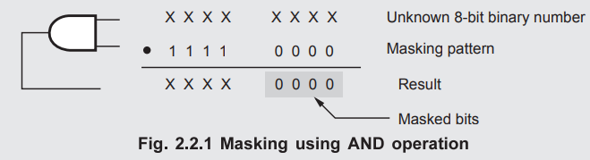
The AND operation clears bits of a binary number. The task of clearing a bit in a binary number is called masking. The Fig. 2.2.1 shows the process of masking.
Addressing Mode : Register Flags Affected : All, CY = 0 AC = 0
Machine Cycles : OF, MR
XRA r Operation : A ← A ⊕ r Bytes : 1
Description : This instruction logically XORs the contents of the specified register with the contents of accumulator and stores the result in the accumulator. The register r is 8-bit general purpose register such as A, B, C, D, E, H and L.
Example : A = 1010 1010 (AAH), C = 0010 1101 (2DH)
XRA C ; This instruction will logically XOR the contents of C register with the contents of accumulator. It will store the result (87H) in the accumulator.
1010 1010
0010 1101
-------------
1000 0111 = (87H)
Addressing Mode : Register Flags Affected : All, CY = 0 AC = 0
Machine Cycles : OF
XRA M Operation : A ← A ⊕ M Bytes : 1
Description : This instruction logically XORs the contents of memory location pointed by HL register pair with the contents of accumulator. The HL register pair is used as a memory pointer.
Example : A = 0101 0101 (55H), HL = 2050H and (2050H) ^ 1011 0011 (B3H)
XRA M ; This instruction will logically XOR the contents of memory location pointed by HL register pair (2050H) i.e. data B3H with the contents of accumulator (55H). It will store the result (E6H) in the accumulator.
01 0 1 0 10 1
10 1 1 00 11
------------------
1110 0110 = E6H
Addressing Mode : Register Indirect Flags Affected : All, CY = 0 AC = 0
Machine Cycles : OF, MR
XRI data Operation : A ← A ⊕ data (8) Bytes : 2
Description : This instruction logically XORs the 8 bit data given in the instruction with the contents of the accumulator and stores the result in the accumulator.
Example : A = 10110011 (B3H)
XRI 39H ; This instruction will logically XOR the contents of accumulator (B3H) with 39H. It will store the result (8AH) in the accumulator.
1011 0011
0011 1001
----------------
1000 1010 = 8AH
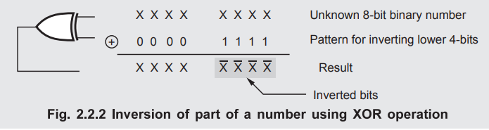
The XOR instruction is used if some bits of a register or memory location must be inverted. This or complemented. This is illustrated in Fig. 2.2.2
Addressing Mode : Immediate Flags Affected : All, CY = 0 AC = 0
Machine Cycles : OF, MR
ORA r Operation : A ← A v r Bytes : 1
Description : This instruction logically ORs the contents of specified register with the contents of accumulator and stores the result in the accumulator. Each bit in the accumulator is ORed with corresponding bit in register r. i.e. DQ bit in accumulator is ORed with Do bit in register r, in A with in r and so on upto D7 bit. The register r is 8-bit general purpose register such as A, B, C, D, E, H and L.
Example : A = 1010 1010 (AAH), B = 0001 0010 (12H)
ORA B ; This instruction will logically OR the contents of B register with the contents of accumulator. It will store the result (BAH) in the accumulator.
1010 1010
0001 0010
---------------
1011 1010 = BAH
Addressing Mode : Register Flags Affected : AU, CY = 0 AC = 0
Machine Cycles : OF
ORA M Operation : A ← A ∨ M Bytes : 1
Description : This instruction logically ORs the contents of memory location pointed by HL register pair with the contents of accumulator. The result is stored in the accumulator. The HL register pair is used as a memory pointer.
Example : A = 0101 0101 (55H), HL = 2050H and (2050H) ^ 1011 0011 (B3H)
ORA M ; This instruction will logically OR the contents of memory location pointed by HL register pair (B3H) with the contents of accumulator (55H). It will store the result (F7H) in the accumulator.
0101 0101
1011 0011
----------------
1111 0111= F7H
Addressing Mode : Register Indirect Flags Affected : All, CY = 0 AC = 0
Machine Cycles : OF, MR
Description : This instruction logically ORs the 8 bit data given in the instruction with the contents of the accumulator and stores the result in the accumulator.
Example : A = 1011 0011 (B3H)
ORI 08H ; This instruction will logically OR the contents of accumulator (B3H) with 08H. It will store the result (BBH) in the accumulator.
1011 0011
0000 1000
----------------
1011 1011= BBH
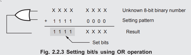
The OR instruction is used to set (make one) any bit in the binary number. This is illustrated in Fig. 2.2.3.
Addressing Mode : Immediate Flags Affected : All, CY = 0 AC = 0
Machine Cycles : OF, MR
CMP r Operation : A - r Bytes : 1
Description : This instruction subtracts the contents of the specified register from contents of the accumulator and sets the condition flags as a result of the subtraction. It sets zero flag if A = r and sets carry flag if A < r. The register r is 8-bit general purpose register such as A, B, C, D, E, H and L.
Example : A = 1011 1000 (B8H) and D = 1011 1001 (B9H)
CMP D ; This instruction will compare the contents of D register with the contents of accumulator. Here A < D so carry flag will set after the execution of the instruction.
Addressing Mode : Register Flags Affected : All
Machine Cycles : OF
CMP M Operation : A - M Bytes : 1
Description : This instruction subtracts the contents of the memory location specified by HL register pair from the contents of the accumulator and sets the condition flags as a result of subtraction. It sets zero flag if A = M and sets carry flag if A < M. The HL register pair is used as a memory pointer.
Example : A = 1011 1000 (B8H), HL = 2050H and (2050H) = 1011 1000 (B8H)
CMP M ; This instruction will compare the contents of memory location (B8H) and the contents of accumulator. Here A = M so zero flag will set after the execution of the instruction.
Addressing Mode : Register Indirect Flags Affected : All
Machine Cycles : OF, MR
CPI data Operation : A - data (8) Bytes : 2
Description : This instruction subtracts the 8 bit data given in the instruction from the contents of the accumulator and sets the condition flags as a result of subtraction. It sets zero flag if A = data and sets carry flag if A < data.
Example : A = 1011 1010 (BAH)
CPI 30H ; This instruction will compare 30H with the contents of accumulator (BAH). Here A > data so zero and carry both flags will reset after the execution of the instruction.
Addressing Mode : Immediate Flags Affected : All
Machine Cycles : OF, MR
STC Operation : CY ← 1 Bytes : 1
Description : This instruction sets carry flag = 1
Example : Carry flag = 0
STC ; This instruction will set the carry flag = 1
Addressing Mode : Implied Flags Affected : CY
Machine Cycles : OF
CMC Operation :  Bytes : 1
Description : This instruction complements the carry flag.
Example : Carry flag = 1
CMC ; This instruction will complement the carry flag i.e. carry flag = 0
Addressing Mode : Implied Flags Affected : CY
Machine Cycles : OF
CMA Operation :  Bytes : 1
Description : This instruction complements each bit of the accumulator.
Example : A = 1000 1000 (88H)
CMA ; This instruction will complement each bit of accumulator i.e. A = 0111 0111 (77H)
Addressing Mode : Implied Flags Affected : None
Machine Cycles : OF
4. Rotate Group
RLC Operation : Bi + 1 ← Bi, B0 ← B7 CY ← B7 Bytes : 1
Description : This instruction rotates the contents of the accumulator left by one position. Bit B 7 is placed in Bo as well as in CY.
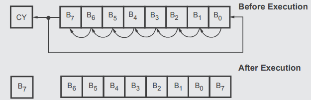
Example : A = 01010111 (57H) and CY = 1
RLC ; After execution of the instruction the accumulator contents will be (1010 1110) AEH and carry flag will reset.
Addressing Mode : Implied Flags Affected : CY
Machine Cycles : OF
RRC Operation : Bi + 1 ← Bi, B7 ← B0 CY ← B0 Bytes : 1
Description : This instruction rotates the contents of the accumulator right by one position. Bit B0 is placed in B7 as well as in CY.
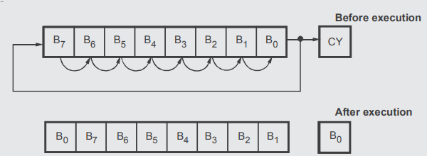
Example : A = 1001 1010 (9AH) and CY = 1
RRC ; After execution of the instruction the accumulator contents will be (0100 1101) 4DH and carry flag will reset.
Addressing Mode : Implied Flags Affected : CY
Machine Cycles : OF
RAL Operation : Bi + 1 ← Bi, B0 ← CY CY ← B7 Bytes : 1
Description : This instruction rotates the contents of the accumulator left by one position. Bit B7 is placed in CY and CY is placed in B0.
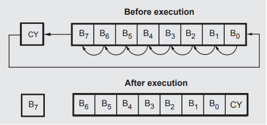
Example : A = 10101101 (ADH) and CY = 0
RAL ; After execution of the instruction accumulator contents will be (0101 1010) 5AH and carry flag will set.
Addressing Mode : Implied Flags Affected : CY
Machine Cycles : OF
RAR Operation : Bi - 1 ← Bi, B7 ← CY CY ← B0 Bytes : 1
Description : This instruction rotates the contents of the accumulator right by one position. Bit B0 is placed in CY and CY is placed in B7.
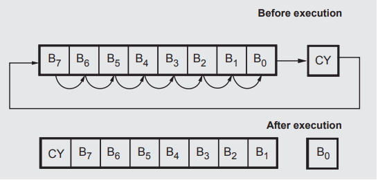
Example : A = 1010 0011 (A3H) and CY = 0
RAR ; After execution of the instruction accumulator contents will be (0101 0001) 51H and carry flag will set.
Addressing Mode : Implied Flags Affected : CY
Machine Cycles : OF
5. Stack Operations
The stack is a portion of read/write memory set aside by the user for the purpose of storing information temporarily. When the information is written on the stack, the operation is called PUSH. When the information is read from stack, the operation is called POP.
The first information pushed on to the stack is the last information popped off from the stack. This type of operation is known as a first in, last out (FILO). This stack is implemented with the help of special memory pointer register. The special pointer register is called the stack pointer. During PUSH and POP operation, stack pointer register gives the address of memory where the information is to be stored or to be read. The stack pointer's contents are automatically manipulated to point to stack top. The memory location currently pointed by stack pointer is called top of stack.
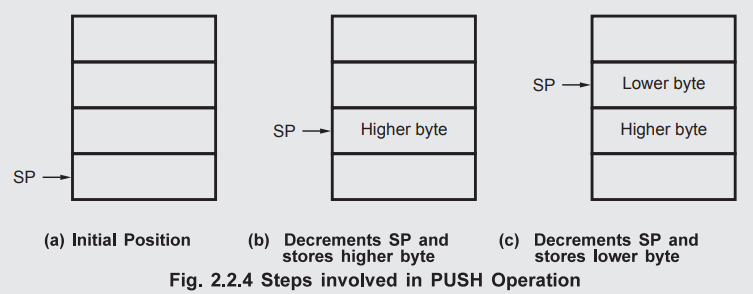
PUSH rp Operation : SP ← SP - 1, (SP) ← rpH, Bytes : 1
SP ← SP - 1, (SP) ← rpL
Description : This instruction decrements stack pointer by one and copies the higher byte of the register pair into the memory location pointed by stack pointer. It then decrements the stack pointer again by one and copies the lower byte of the register pair into the memory location pointed by stack pointer. The rp is 16-bit register pair such as BC, DE, HL. Only higher order register is to be specified within the instruction.
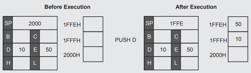
Example : SP = 2000H, DE = 1050H.
PUSH D ; This instruction will decrement the stack pointer (2000H) by one (SP = 1FFFH) and copies the contents of D register (10H) into the memory location 1FFFH. It then decrements the stack pointer again by one (SP = 1FFEH) and copies the contents of E register (50H) into the memory location 1FFEH.
Addressing Mode : Register Indirect Flags Affected : None
Machine Cycles : OF, MW, MW
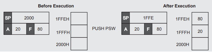
PUSH PSW Operation : SP ← SP - 1, (SP) ← A Bytes : 1
SP ← SP - 1, (SP) ← Flag register
Description : This instruction decrements stack pointer by one and copies the accumulator contents into the memory location pointed by stack pointer. It then decrements the stack pointer again by one and copies the flag register into the memory location pointed by the stack pointer.
Example : SP = 2000H, A = 20H, Flag register = 80H
PUSH PSW ; This instruction decrements the stack pointer (SP = 2000H) by one (SP = 1FFFH) and copies the contents of the accumulator (20H) into the memory location 1FFFH. It then decrements the stack pointer again by one (SP = 1FFEH) and copies the contents of the flag register (80H) into the memory location 1FFEH.
Addressing Mode : Register Indirect Flags Affected : None
Machine Cycles : OF, MW, MW
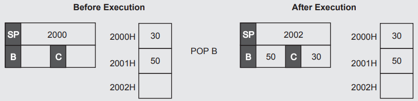
POP rp Operation : rpL ← (SP), SP ← SP + 1, Bytes : 1
rpH ← (SP), SP ← SP + 1
Description : This instruction copies the contents of memory location pointed by the stack pointer into the lower byte of the specified register pair and increments the stack pointer by one. It then copies the contents of memory location pointed by stack pointer into the higher byte of the specified register pair and increments the stack pointer again by one. The rp is 16-bit register pair such as BC, DE, HL. Only higher order register is to be specified within the instruction.
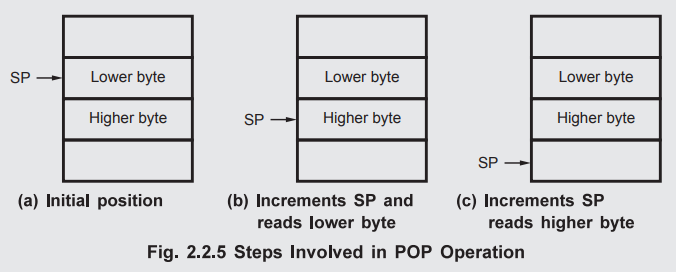
Example : SP = 2000H, (2000H) = 30H, (2001H) = 50H
POP B ; This instruction will copy the contents of memory location pointed by stack pointer, 2000H (i.e. data 30H) into the C register. It will then increment the stack pointer by one, 2001H and will copy the contents of memory location pointed by stack pointer, 2001H (i.e. data 50H) into B register, and increment the stack pointer again by one.
Addressing Mode : Register Indirect Flags Affected : None
Machine Cycles : OF, MR, MR
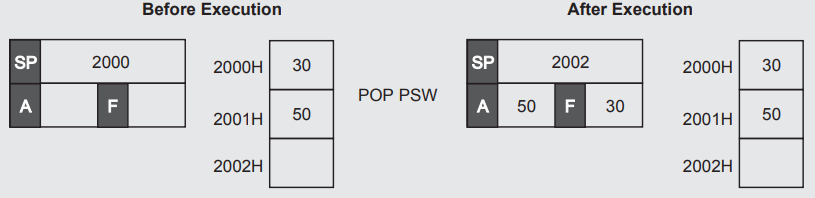
POP PSW Operation : Flag register ← (SP), SP ← SP + 1, Bytes : 1
A ← (SP), SP ← SP + 1
Description : This instruction copies the contents of memory location pointed by the stack pointer into the flag register and increments the stack pointer by one. It then copies the contents of memory location pointed by stack pointer into the accumulator and increments the stack pointer again by one.
Example : SP = 2000H, (2000H) = 30H, (2001H) = 50H
POP PSW ; This instruction will copy the contents of memory location pointed by the stack pointer, 2000H (i.e. data 30H) into the flag register. It will then increment the stack pointer by one, 2001H and will copy the contents of memory location pointed by stack pointer into the accumulator and increment the stack pointer again by one.
Addressing Mode : Register Indirect Flags Affected : None
Machine Cycles : OF, MR, MR
SPHL Operation : SP ← HL Bytes : 1
Description : This instruction copies the contents of HL register pair into the stack pointer. The contents of H register are copied to higher order byte of stack pointer and contents of L register are copied to the lower byte of stack pointer.
Example : HL = 2500H
SPHL ; This instruction will copy 2500H into stack pointer. So after execution of instruction stack pointer contents will be 2500H.
Addressing Mode : Register Flags Affected : None
Machine Cycles : OF
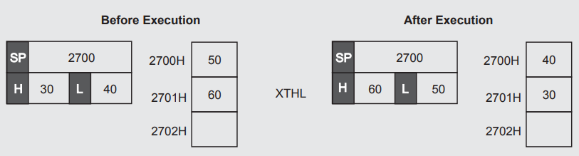
XTHL Operation : L ↔ (SP), H ↔ (SP + 1) Bytes : 1
Description : This instruction exchanges the contents of memory location pointed by the stack pointer with the contents of L register and the contents of the next memory location with the contents of H register. This instruction does not modify stack pointer contents.
Example : HL = 3040H and SP = 2700H, (2700H) = 50H, (2701H) = 60H
XTHL ; This instruction will exchange the contents of L register (40H) with the contents of memory location 2700H (i.e. 50H) and the contents of H register (30H) with the contents of memory location 2701H (i.e. 60H).
Addressing Mode : Register Indirect Flags Affected : None
Machine Cycles : OF, MR, MR, MW, MW
6. Branch Group
JMP addr Operation : PC ← addr Bytes : 3
Description : This instruction loads the PC with the address given within the instruction and resumes the program execution from this location.
Example : JMP 2000H ; This instruction will load PC with 2000H and processor will fetch next instruction from this address.
Addressing Mode : Immediate Flags Affected : None
Machine Cycles : OF, MR, MR
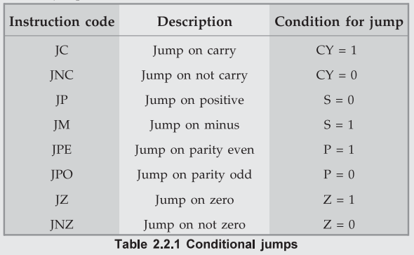
Jcond addr Operation : If condition true PC ← addr Bytes : 3
Description : This instruction causes a jump to an address given in the instruction if the desired condition occurs in the program before the execution of the instruction. The Table 2.2.1 shows the possible conditions for jumps.
Example : Carry flag = 1
JC 2000H ; This instruction will cause a jump to an address 2000H i.e. program counter will load with 2000H since CF =1.
Addressing Mode : Immediate Flags Affected : None
Machine Cycles : OF, MR, MR
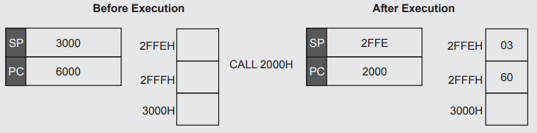
CALL addr Operation : (SP - 1) ← PCH, (SP - 2) ← PCL, Bytes : 3
SP ← SP - 2, PC ← addr
Description : A subroutine is a group of instructions, performs a particular subtask which is executed number of times. It is written separately. The microprocessor executes this subroutine by transferring program control to the subroutine program. After completion of subroutine program execution, the program control is returned back to the main program.
The CALL instruction is used to transfer program control to a subprogram or subroutine. This instruction pushes the current PC contents onto the stack and loads the given address into the PC. Thus the program control is transferred to the address given in the instruction. Stack pointer is decremented by two.
When the subroutine is called, the program control is transferred from calling program to the subroutine. After execution of subroutine it is necessary to transfer program control back to the calling program. To do this processor must remember the address of the instruction next to the CALL instruction. Processor saves this address on the stack when the CALL instruction is executed.
Note : The stack is a part of read/write memory set aside for storing intermediate results and addresses.
Example : Stack pointer = 3000H.
6000H CALL 2000H ; This instruction will store the address of instruction next to CALL (i.e. 6003H) on the stack and load PC with 2000H.
Addressing Mode : Immediate Flags Affected : None
Machine Cycles : OF, MR, MR, MW, MW
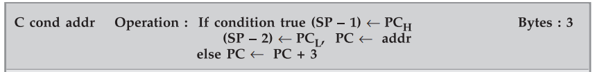
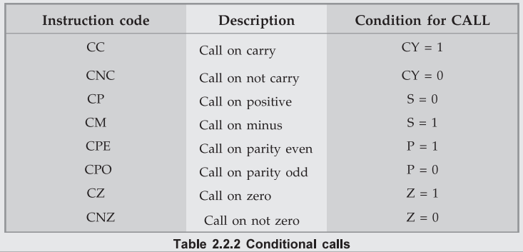
Description : This instruction calls the subroutine at the given address if a specified condition is satisfied. Before call it stores the address of instruction next to the call on the stack and decrements stack pointer by two. The Table 2.2.2 shows the possible conditions for calls.
Example : Carry flag = 1, stack pointer = 4000H.
2000H CC 3000H; This instruction will store the address of the next instruction i.e. 2003H on the stack and load the program counter with 3000H, since the carry flag is set.
Addressing Mode : Immediate Flags Affected : None
Machine Cycles : OF, MR, MR MW, MW
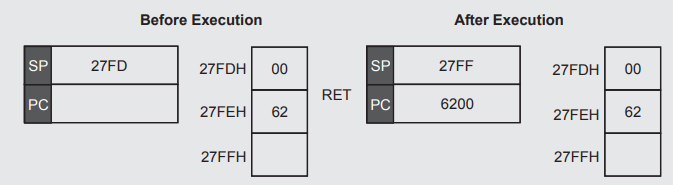
RET Operation : PCL ← (SP), PCH ← (SP+1), SP ← SP + 2 Bytes : 1
Description : This instruction pops the return addr (address of the instruction next to CALL in the main program) from the stack and loads program counter with this return address. Thus transfers program control to the instruction next to CALL in the main program.
Example : If SP = 27FDH and contents on the stack are as shown then
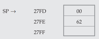
RET ; This instruction will load PC with 6200H and it will transfer program control to the address 6200H. It will also increment the stack pointer by two.
Addressing Mode : Register Indirect Flags Affected : None
Machine Cycles : OF, MR, MR
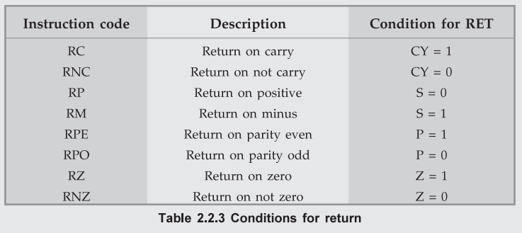
R condition Operation : If condition true PCL ← (SP), Bytes : 1
PCH ← (SP + 1), SP ← SP + 2
Description : This instruction returns the control to the main program if the specified condition is satisfied. Table 2.2.3 shows the possible conditions for return.
Addressing Mode : Register Indirect Flags Affected : None
Machine Cycles : OF, MR, MR
PCHL Operation : PC ← HL Bytes : 1
Description : This instruction loads the contents of HL register pair into the program counter. Thus the program control is transferred to the location whose address is in HL register pair.
Example : HL = 6000H;
PCHL ; This instruction will load 6000H into the program counter.
Addressing Mode : Register Flags Affected : None
Machine Cycles : OF (6-T-states)
RST n Operation : (SP - 1) ← PCH, (SP - 2) ← PCL Bytes : 1
SP ← SP - 2, PC ← (n × 8) in hex
Description : This instruction transfers the program control to the specific memory address as shown in Table 2.2.4. This instruction is like a fixed address CALL instruction. These fixed addresses are also referred to as vector addresses. The processor multiplies the RST number by 8 to calculate these vector addresses. Before transferring the program control to the instruction following the vector address RST instruction saves the current program counter contents on the stack like CALL instruction.
Instruction code Vector address
RST 0 0 × 8 = 0000H
RST 1 1 × 8 = 0008H
RST 2 2 × 8 = 0010H
RST 3 3 × 8 = 0018H
RST 4 4 × 8 = 0020H
RST 5 5 × 8 = 0028H
RST 6 6 × 8 = 0030H
RST 7 7 × 8 = 0038H
Table 2.2.4 Vector addresses for return instructions
Example : SP = 3000H
2000H RST 6 ; This instruction will save the current contents of the program counter (i.e. address of next instruction 2001H) on the stack and it will load the program counter with vector address 6 x 8 = 4810= 30H) 0030H.
Addressing Mode : Register Indirect Flags Affected : None
Machine Cycles : OF (6-T-states), MW, MW
7. Input / Output
IN addr(8-bit) Operation : A ← (addr) Bytes : 2
Description : This instruction copies the data at the port whose address is specified in the instruction into the accumulator.
Example : Port address = 80H, data stored at port address 80H, (80H) = 10H
IN 80H ; This instruction will copy the data stored at address 80H, i.e. data 10H in the accumulator.
Addressing Mode : Direct Flags Affected : None
Machine Cycles : OF, MR, I/O Read
OUT addr(8-bit) Operation : (addr) ← A Bytes : 2
Description : This instruction sends the contents of accumulator to the output port whose address is specified within the instruction.
Example : A = 40H
OUT 50H ; This instruction will send the contents of accumulator(40H) to the output port whose address is 50H.
Addressing Mode : Direct Flags Affected : None
Machine Cycles : OF, MR, I/O Write
8. Operation Control Group
EI Operation : IE (F/F) ← 1 Bytes : 1
Description : This instruction sets the interrupt enable flip flop to enable interrupts. When the microprocessor is reset or after interrupt acknowledge, the interrupt enable flip-flop is reset. This instruction is used to reenable the interrupts.
Addressing Mode : Implied Flags Affected : None
Machine Cycles : OF
DI Operation : IE (F/F) ← 0 Bytes : 1
Description : This instruction resets the interrupt enable flip-flop to disable interrupts. This instruction disables all interrupts except TRAP since TRAP is non-maskable interrupt (cannot be disabled. It is always enabled).
Addressing Mode : Implied Flags Affected : None
Machine Cycles : OF
NOP Operation : No operation is performed Bytes : 1
Description : No operation is performed.
Addressing Mode : Implied Flags Affected : None
Machine Cycles : OF
HLT Operation : Halts the processor Bytes : 1
Description : This instruction halts the processor. It can be restarted by applying a RESET signal. a valid interrupt or by
Addressing Mode : Implied Flags Affected : None
Machine Cycles : OF + Wait states until Reset or Interrupt
SIM Operation : Serial interrupt mask Bytes : 1
Description : This instruction masks the interrupts as desired. It also sends out serial data through the SOD pin. For this instruction command byte must be loaded in the accumulator.
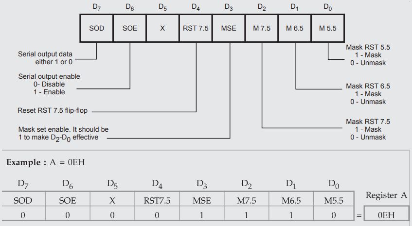
SIM ; This instruction will mask RST 7.5 and RST 6.5 interrupts whereas RST 5.5 interrupt will be unmasked. It will also disable serial output.
Addressing Mode : Implied Flags Affected : None
Machine Cycles : OF
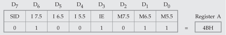
RIM Operation : Read interrupt mask Bytes : 1
Description : This instruction copies the status of the interrupts into the accumulator. It also reads the serial data through the SID pin.
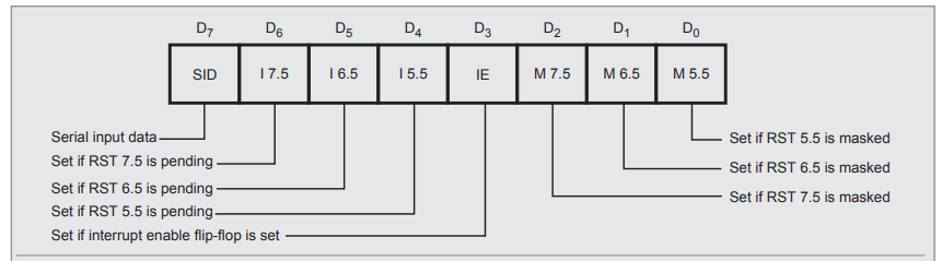
Example : RIM ; After execution of RIM instruction if the contents of accumulator are 4BH then we get following information.
Addressing Mode : Implied Flags Affected : None
Machine Cycles : OF
Review Questions
1. Explain the operations carried out when 8085 executes the instructions,
i) MOV A, M ii) XCHG Ui) DAD B iv) DAA
AU : Dec.-07, Marks 16
2. With suitable examples, explain the function of various data transfer and data manipulation instructions of 8085.
AU : May-10,11, Marks 10
3. How are the 8085 instructions classified according to the functional categories ?
AU : Dec.-11, Marks 2
4. Describe with suitable examples the data transfer, loading and storing instructions.
AU : June-12, Marks 8
5. What is stack ? And what is the function of stack pointer?
AU : Dec.-07, Marks 2
6. Explain the operations carried out when 8085 executes the instructions. POP PSW
AU : Dec.-07, Marks 16
7. Discuss the organizations of the 8085 stack and the various instructions that will operate on the stack.
AU : Dec-09, June-11, Marks 10
8. Describe with a suitable example the operation of stack.
AU : June-12, Marks 8
9. What is meant by subroutine ? Explain how the stack is affected while calling a subroutine program.
AU : May-17, Marks 8
10. How is PUSH B instruction executed ? Find the status after the execution.
AU : May-11, Marks 2
11. Explain the sequence of events in the execution of CALL and RET instructions.
12. What is the use of branching instructions ? Give Example.
13. State the function of given 8085 instructions: JP, JPE, JPO, JNZ
14. Give examples for machine control instructions.
AU : June-11, May-13, Marks 2^
15. Give two examples for data transfer instructions, arithmetic instructions, logic instructions and branch instructions.
AU : Dec -12, Marks 8
16. Describe with suitable examples the data transfer instructions in 8085 microprocessor.
AU : May-13, Marks 8
17. Discuss in detail about the 8085 instruction set, explaining about the various types of operations.
AU : Dec.-13, Marks 16
18. Describe the categories of instructions used for data manipulations in 8085 microprocessor.
AU : May-16, Marks 8
19. Explain the logical instructions with examples.
20. Differentiate RAL and RLC instruction.
AU : Dec.-16, Marks 8
Microprocessors and Microcontrollers: Unit II: (a) 8085 Instruction Set and ALP : Tag: : - Instruction Set of 8085
Related Topics
Related Subjects
Microprocessor and Microcontroller
EE3404 MCU 4th Semester EEE Dept | 2021 Regulation | 4th Semester EEE Dept 2021 Regulation