Electron Devices and Circuits: Unit III: (b) MOSFET Amplifier
Internal Capacitances of MOSFET and High Frequency Model
• Gate capacitance : It is a parallel-plate capacitance formed by a gate electrode with the channel, with the oxide layer acts as a capacitor dielectric. It is denoted as Cox.
Internal Capacitances of MOSFET and High Frequency Model
•
High frequency response of MOSFET affects due to internal capacitances.
•
There are two types of internal capacitances in the MOSFET :
•
Gate capacitance : It is a parallel-plate capacitance
formed by a gate electrode with the channel, with the oxide layer acts as a
capacitor dielectric. It is denoted as Cox.
•
Junction capacitances (Source-body and drain-body depletion layer capacitances)
: These capacitances are due to the reverse-biased pn junctions formed by the n
+ source region and the p-type substrate, and the n + drain region and the
p-type substrate. These are denoted as source diffusion capacitance and drain
diffusion capacitance, respectively.
1. Gate Capacitances
There
are three gate capacitances : Cgs, Cgd and Cgb"
Values
of gate capacitances
•
In triode region, the channel has uniform depth and hence we have
Cgs,
= Cgd = 1/2 WL Cox (Triode region)
•
In saturation region, the channel has a tapered shape and is pinched off at or
near the drain. Therefore, we have
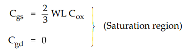
•
In cut-off region, the channel disappears and thus
Cgs,
= Cgd = D (cut-off)
However,
gate-body model capacitance is given by
Cgb
= W Lov Cox (cut-off)
•
Due to the fact that the source and drain diffusions extend slightly under the
gate oxide we need to add the capacitive component (Cov) to the Cgs
and Cgd in the above formulas. The component Cov is known as overlap
capacitance and is given by
Cov
= W Lov Cox
where
Lov is the overlap length and is typically 0.05 L to 0.1 L.
2. Junction Capacitances
•
Source diffusion capacitance is given by
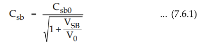
where
Csb0 is the value of Csb at zero body-source bias, VSB is the
magnitude of the reverse-bias voltage, and V0 is the junction built-in voltage,
typically 0.6 V to 0.8 V.
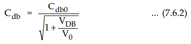
•
Similarly, drain diffusion capacitance is given by
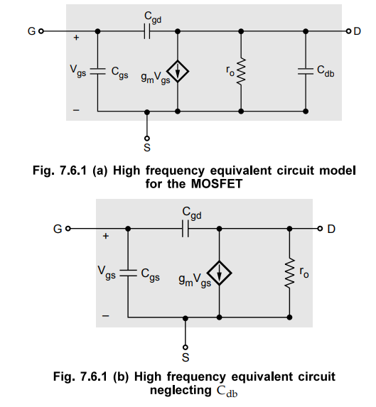
3. High-Frequency MOSFET Model
•
Fig. 7.6.1 shows the high frequency equivalent circuit model for MOSFET. In
this model, capacitance Cdb can be neglected to simplify the analysis. The resulted
model is shown in Fig. 7.6.1 (b).
4. Unity-Gain Frequency (fT)
•
The fT is the frequency at which the short-circuit current gain of
the CS MOSFET amplifier becomes unity.
•
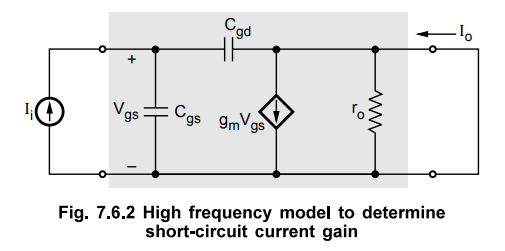
Fig. 7.6.2 shows the modified high-frequency equivalent circuit to determine
the short-circuit current gain. Here, the input is fed with a current-source
signal Ii and the output terminals are shorted.
•
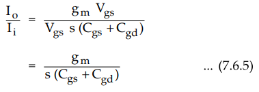
The short circuit current Io is given by
Io
= gm Vgs – s Cgd Vgs
•
The second term in the above equation is very small and can be neglected at the
frequencies of interest and thus
Io
= gm Vgs ...
(7.6.3)
•
The Vgs m terms of Ii can be given by
Vgs
= Ii / s (Cgs Vgd ) ...(7.6.4)
•
Substituting the values of Ii and Io from equations (7.6.3) and (7.6.4) we have
•
For physical frequencies S = j rn From equation (7.6.5) it can be seen that the
magnitude of the current becomes unity at the frequency.

•
From equation (7.6.7) we can say that fT is proportional to gm and inversely
proportional to the internal capacitances.
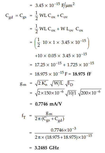
Ex. 7.6.1 For n-channel MOSFET, L = 1.0 µm Lgv = 0.05 µm W=10µm Cox =3.45 × 10⁻³ F / m2, ID = 200 µA and Kn = 150 µA/ V2. Find the fT if MOSFET is operating in the triode region.
Sol.
: Cox = 3.45 ×
10-3 F/m2
Electron Devices and Circuits: Unit III: (b) MOSFET Amplifier : Tag: : - Internal Capacitances of MOSFET and High Frequency Model
Related Topics
Related Subjects

Electron Devices and Circuits
EC3301 3rd Semester EEE Dept | 2021 Regulation | 3rd Semester EEE Dept 2021 Regulation