Linear Integrated Circuits: Unit III: Applications of Op-amp
Introduction to Bandpass Filters using Op-amp
Working Principle, Circuit Diagram, Solved Example Problems | Operational amplifier
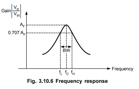
Thus, the pass band is between the two cut-off frequencies fH and fL where fH > fL. Any frequency outside this band gets attenuated.
Introduction to Bandpass Filters
A
bandpass filter is basically a frequency selector. It allows one particular
band of frequencies to pass. Thus, the pass band is between the two cut-off
frequencies fH and fL where fH > fL.
Any frequency outside this band gets attenuated. The frequency response of band
pass filter is shown in Fig. 3.10.1.
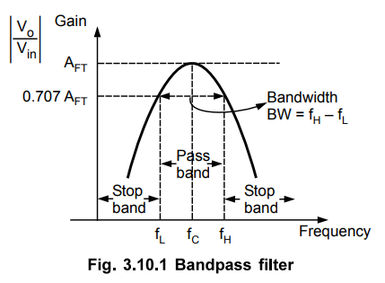
The
pass band which is between fH and fL is called bandwidth
of the filter denoted as BW.
BW
= fH - fL ….. (3.10.1)
The
frequency at the centre of the pass band is called centre frequency denoted as
fC.
The
gain is maximum at fC and is denoted as AFT called total
passband gain.
Practically,
the fC is not exactly at the centre of the pass band hence, it is
also called as resonant frequency. The gain at fL and fH is
0.707 AFT.
There
are two types of bandpass filters which are classified based on the figure of
merit or quality factor (Q).
i)
For Q < 10, the bandpass filter is called wide bandpass filter. In this type,
the bandpass is wide and we get large bandwidth. The response is shown in the
Fig. 3.10.2 (a).
ii)
For Q > 10, the bandpass filter is called narrow bandpass filter. The
bandpass is very narrow and the bandwidth is very small. Higher the value of Q,
narrower is the passband and more selective is the filter. In the narrow band
filter, the gain peaks at the centre frequency. The response is shown in Fig.
3.10.2 (b).
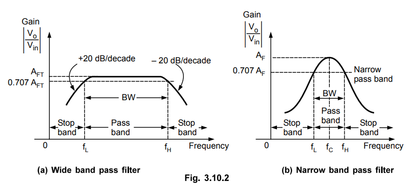
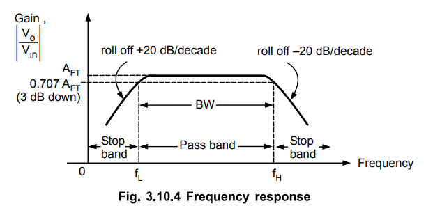
The
gain roll off for f < fL is + 20 dB/decade while f > fH
it is - 20 dB/decade.
For
wide band pass filter, the centre frequency is given by,
fC
= √fL fH …
(3.10.2)
The
relationship between Q and 3 dB bandwidth with fc is given by,
Q
= fC / BW = FC / fH – fL … (3.10.3)
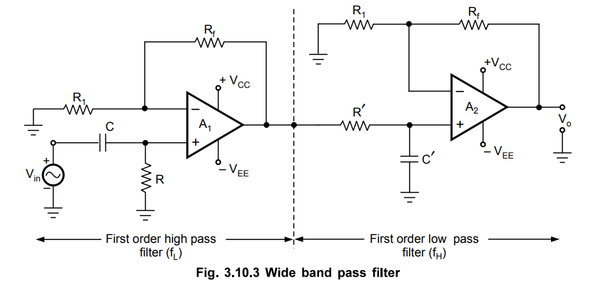
1. Wide Band Pass Filter
The
wide band pass filter can be realised by simply cascading a high pass filter
and low pass filter. If both high pass and low pass filters are of first order,
the gain roll off in both the stop bands are ± 20 dB/decade and wide band pass
filter is of first order. To get gain roll off ± 40 dB/decade and second order
wide band pass filter, both high pass and low pass filters must be of second
order and so on.
The
Fig. 3.10.3 shows the first order wide band pass filter obtained by cascading
first order high pass and low pass filter sections.
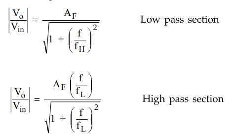
For
wide band pass response, fH must be greater than fL. The
voltage gain expressions for the two sections are reproduced here for the
convenience.
The
design steps discussed earlier for first order low pass and high pass filters,
are to be used to design the wide band pass filter of first order.
As
the two circuits are in cascade, the overall gain of wide band pass filter is
the product of the two gains expressed as,
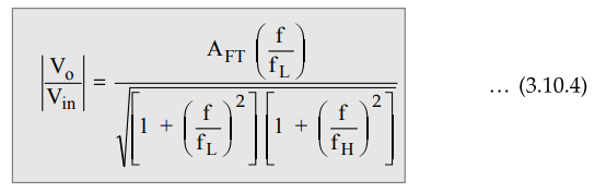
where AFT = Total pass band gain
f
= Input frequency in Hz
fL
= Lower cut off frequency in Hz
fH
= Higher cut-off frequency in Hz
and AFT = A1 A2
…. (3.10.5)
where
A1
= Gain of high pass section
A2
= Gain of low pass section
The
frequency response for such a first order wide band pass filter is shown in the
Fig. 3.10.4
2. Narrow Band Pass Filter
The
narrow band pass filter uses only one op-amp as against two by wide band pass
filter. It has following features :
i)
It has two feedback paths.
ii)
The op-amp is in the inverting configuration.
Due
to the two feedback paths, it is called multiple feedback filter.
The
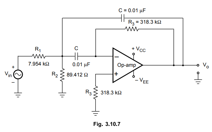
Fig. 3.10.5 shows the circuit diagram of narrow band pass filter.
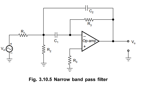
As
seen from Fig. 3.10.5, the input is applied to the inverting input terminal.
Thus, op-amp is in inverting configuration. The resistance R3
connected to non-inverting input terminal is offset compensating resistance.
The
important parameters of the narrow band pass filter are fL' fH'
the center frequency fC' the gain at the center frequency AF and the
quality factor Q.
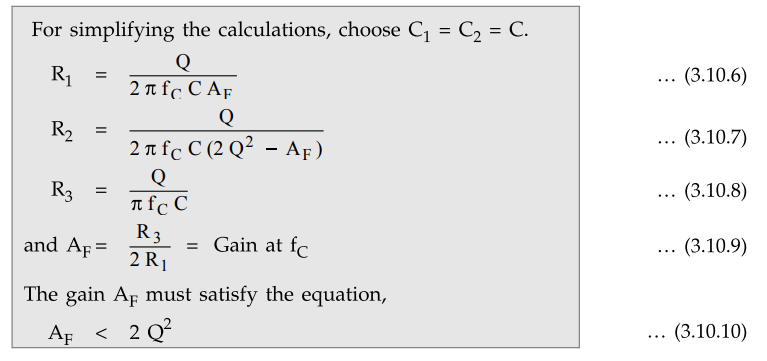
The
relationship of components with the various parameters are given by the
following expressions.
Changing
the centre frequency fC :
Let fC = Original frequency
fC
= New centre frequency
The
new centre frequency can be achieved by changing the resistance R2.
The new value of resistance say R2, can be obtained as,
R2
= R2 (fC / fC ) ... (3.10.11)
This
is an important advantage of the multiple feedback circuit, that fC
can be changed without changing gain AF or bandwidth BW.
The
frequency response of the narrow band pass filter is shown in Fig. 3.10.6.
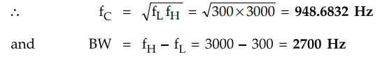
Example
3.10.1 A bandpass filter has lower and upper cut-off
frequencies of 300 Hz and 3000 Hz. Find the bandwidth and the resonant
frequency.
May-05,
Marks 6
Solution
:
fL = 300 Hz, fH =
3000 Hz
The
centre frequency fC is also called resonant frequency.
Example
3.10.2 Design a narrow band pass filter with fC =
3kHz,Q = 30,AF = 20. Assume C1 = C2 = C
Solution
:
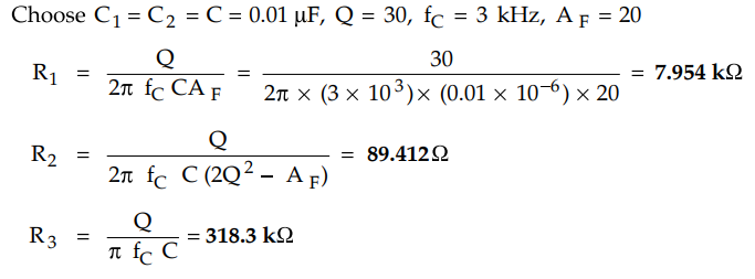
The
designed circuit is shown in the Fig. 3.10.7
Review Questions
1. What is band pass
filter ? Which are the two types of band pass filters ?
2. Explain with neat
diagram, the operation of wide band pass filter.
3. Explain with neat
diagram, the operation of narrow band pass filter.
4. Design a wide band
pass filter with fL = 200 Hz and fH =l kHz and a pass
band gain = 4.
Draw the frequency
response and calculate its Q value.
[ Ans.: Q = 0.56 ]
Linear Integrated Circuits: Unit III: Applications of Op-amp : Tag: : Working Principle, Circuit Diagram, Solved Example Problems | Operational amplifier - Introduction to Bandpass Filters using Op-amp
Related Topics
Related Subjects

Linear Integrated Circuits
EE3402 Lic Operational Amplifiers 4th Semester EEE Dept | 2021 Regulation | 4th Semester EEE Dept 2021 Regulation