Electrical Machines II: UNIT V: b. Special Machines
Introduction to Magnetic Levitation
Two fundamental principles are involved for studying the concept of magnetic levitation. The first principle is in the form of a law which is suggested by Michael Faraday commonly known as Faraday's laws of electromagnetic induction.
Introduction to Magnetic Levitation
The
magnetic levitation is based on the creation of magnetic forces which exist
because of various things. It can either be caused by a permanent magnet made
up of solid material with induced north and south pole or the other way through
which a magnetic field established is through an electric field changing
linearly with time. Yet another way to create a magnetic field is through the
use of direct current.
Two
fundamental principles are involved for studying the concept of magnetic
levitation. The first principle is in the form of a law which is suggested by
Michael Faraday commonly known as Faraday's laws of electromagnetic induction.
Faraday's
law states that if there is a change in the magnetic field on a coil of wire, a
change in voltage is observed. It can also be said that with change in voltage,
a change in magnetic field occurs. This is due to induced current in the coil
as a result of that change in voltage. The strength of the magnetic field is
proportional to current flowing through coil. It current is higher, stronger
magnetic field is produced with greater magnetic forces.
The
direction of magnetic forces is given using Lenz's law which states that the
emf induced in an electric circuit always acts in such a way that the current
driven by it in the circuit will oppose the change in the magnetic flux
producing the emf. This means that if a current is induced in the coil then the magnetic
field produced will be prependicular to the direction of current. Due to
prediction of direction of magnetic field, it can be maximized by setting up a
suitable set up and magnetic levitation finds number of applications such as in
transportation and other industrial applications.
Maglev
is a combination of superconducting magnets and linear motor technology which
in turn realizes super high speed transport system. It is safe, reliable, with
less impact on environment and requires minimum maintenance. In Maglev system,
a vehicle rims levitated from the guide way with use of electromagnetic forces
between superconducting magnets and coils on the ground. Principle of Maglev can
be understood from the Fig. 9.12.1.
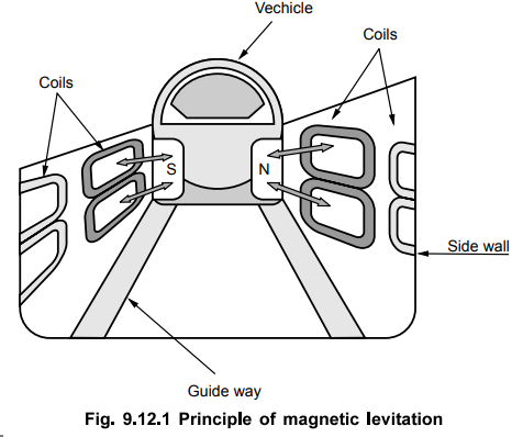
The
coils are installed on the side walls of the guideway. The superconducting
magnets are attached to the vehicle itself. Due to high speed of vehicle, there
is induced current in the coils during the instant when it passes the coils.
The coils act as electromangets for small duration. Due to the interaction
between the coils on the guide way and the magnets on the vehicle allows the
vehicle to stay levitated above a track for a few centimeters. One side of
vehicle experiences a magnetic force tending to push it from the bottom while
at the same time, there is pulling force from the top part of coil which pulls
the other side of the vechicle away from the coil. This forms basis for levitation
principle for the track. It is also required to take proper care so that the
vehicle does not slide from side to side. Let us try to understand this
levitation principle in detail with various forces involved and their
interactions.
For
simplicity in understanding, let us consider a permanent magnet which is moving
at a speed of v m/s across a conducting ladder as shown in the Fig. 9.12.2.

This
moving magnet tends to drag the conducting ladder along with it because of
application of horizontal tractive force, F = BIl where B is flux
density in Wb/m2,
I
is current flowing through the conductor and l is the active length of
the conductor under the influence of magnetic field. The plane of motion of
magnet and the plane of conducting ladder are perpendicular to each other due
to which maximum force is exerted and its direction can be found using
Fleming's left hand rule.
In
addition to this horizontal tractive force, a vertical force also exists
between the moving magnet and conducting ladder which pushes the magnet away
from the ladder in the upward direction. Let I be the current flowing through
conductor Q. The front view of above figure is shown in the Fig. 9.12.3. Let us
initially assume that the magnet is moving at a low speed.

The
magnetic flux ϕ at the centre of the magnet is maximum so the emf induced in
conductor Q is maximum. If the conductor is assumed to have low inductance then
the induced current will also reach its maximum value approximately at the same
instant when voltage reaches its maximum value. This current flows through
conductors P and R with magnitude I/2 . The currents in conductors P, Q and R
will produce their own magnetic fields, which can be found by using Right hand
rule. These magnetic fields produced by the conductors will interact with the
magnetic field of the magnet so that vertical force is exerted on the magnet.
The front half of magnet is pushed upwards while the rear half of magnet is
pulled downwards. With respect to centre of magnet, this vertical forces of attraction
and repulsion, being equal and opposite, cancels each other due to symmetry and
only horizontal tractive force is present.
Now
let us consider that the magnet is moving at a very high speed. This condition
is represented in the Fig. 9.12.4 with the front view as shown earlier.

Due
to inductance associated with the conductor, current in conductor Q reaches its
maximum value a fraction of time, At, after voltage reaches its maximum value.
This time interval At depends on L/R time constant of conductor circuit. This
delay is very small at low speed such that voltage and current reach their
maximum value virtually at the same time and place. ∆t large speeds, this time
dealy At is sufficient enough to produce a large shift in space between the
points where the voltage and current achieve their maximum values.
By
the time current in Q reaches its maximum value, the centre of magnet is
already ahead of conductor Q by a distance given as vAt. The currents in
conductors P, Q and R are established as explained earlier and their
interaction with the field of magnet exerts a vertical force in such a way that
the front end of magnet is pushed downwards while the rear end is pulled
upwards. This is basic principle of magnetic levitation which means floating in
air.
This
principle is used in ultra high speed trains running at speeds in the range of
300 km/hr and which float in the air about 100 mm to 300 mm above the track.
These trains do not need traditional steel rail and will not require any
wheels.
A
powerful superconducting magnet is mounted at the bottom of the train which
induces current in the rail. This produces a vertical force called levitation force
which keeps the train pushed up in the air above the track.
Linear
induction motor is employed to propel the train. Linear induction motor
consists of a flat stator which produces a flux that moves in a straight line
from its one end to the other at a linear synchronous speed. This speed is
given by,
v
s = 2 w f
where
v s = Linear synchronous speed
W
= Width of one pole pitch in m
f
= Supply frequency in Hz.
The
above speed is independent of number of poles. The rotor consists of a plate
made up of aluminium, or copper or iron. The flux moves linearly and drags the
rotor plate along with it in the same direction. Practically the stator moves
while the rotor plate is kept stationary in the applications.
It
is employed in high speed trains which uses principle of magnetic levitation as
explained earlier. The rotor consists of a thick aluminium plate which is fixed
to the ground and extends over the entire length of the track. The stator which
is linear is bolted in the Fig. 9.12. 5.

The
slip in case of linear induction motor is given as,
Slip,
s = v s – v / v s where v s = 2 wf
And
v = Actual speed in m/s
The
force or thrust exerted is given by,
F
= pm / v s
where
Pin is active power supplied to the rotor. The flow of active power
remains same as that in case of normal induction motor.
Review Question
1. Write a short note on magnetic levitation.
Electrical Machines II: UNIT V: b. Special Machines : Tag: Engineering Electrical Machines - II : - Introduction to Magnetic Levitation
Related Topics
Related Subjects

Electrical Machines II
EE3405 Machine 2 EM 2 4th Semester EEE Dept | 2021 Regulation | 4th Semester EEE Dept 2021 Regulation