Microprocessors and Microcontrollers: Unit V: (a) Microcontroller Applications
Keyboard Interface
Simple and Matrix
Review Questions 1. With a neat circuit diagram explain how a 4×4 keypad is interfaced with 8051 microcontroller 2. Interface an 8×8 keyboard using 8255 ports and write a program to read the code of a pressed key. AU : Dec.-10, Marks 8 3. How do you interface a 4 × 4 matrix keyboard using 8051 microcontroller ? AU : Dec.-11, Marks 8 4. How to interface a 4×4 matrix keyboard using 8051 microcontroller and explain how to identify AU : Dec.-12, Marks 8 5. Show how to interface a 8 × 8 matrix keyboard to the 8051 microcontroller and discuss in detail the various stages for detection and identification cf key activation by a microcontroller. Also, write an assembly language program to detect and identify the pressed key. AU : Dec.-19, Marks 15
Keyboard Interface
AU
: May-07, 08, 11, 18, Dec.-10, 11, 12, 19
1. Simple Keyboard Interface
Fig.
17.1.1 shows simple keyboard interface.

Here
eight keys are individually connected to specific pins of port Pl. Each port
pin gives the status of key connected to that pin. When port pin is logic 1,
key is open, otherwise key is closed.
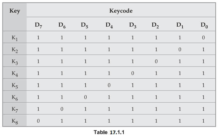
Software
routine to get keycode with key debounce.
START:
MOV A, P1 ; Read key status
;
check if keys are open
CJNE
A,#FFH,START ; if no, goto start
;
otherwise continue
PRO
: LCALL DEBOUNCE_DELAY ; call debounce delay
AGAIN
: MOV A, P1; Read key status
CJNE
A, #FFH PRO1 ; check if any key is
;
pressed
LJMP
AGAIN ; if no, goto AGAIN
;
otherwise
;
continue
PRO1
: LCALL DEBOUNCE_DELAY ; call debounce delay
MOV
A, P1; Get key code
RET
; Return from
;
subroutine
This
program reads status of all keys by getting data through P1 and compares it
with FFH to check whether all keys are open. If all keys are open, instruction
compare sets the zero flag, and the program waits for key debounce. After
waiting about 10 ms, program checks the Pl for key press. If key press is
found, program waits for another 10 ms as a key debounce period. After key
debounce period, program reads the keycode from P1.
2. Matrix Keyboard Interface
In
simple keyboard interface one input line is required to interface one key and
this number will increase with number of keys. Therefore, such technique is not
suitable when it is necessary to interface large number of keys. To reduce
number of connections keys are arranged in the matrix form as shown in the Fig.
17.1.2.
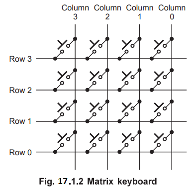
Fig.
17.1.2 shows sixteen keys arranged in
four rows and four columns. When keys are open, row and column do not have any
connection. When a key is pressed, it shorts corresponding one row and one
column. This matrix keyboard requires eight lines to make all the connections
instead of the sixteen lines required if the keys are connected individually,
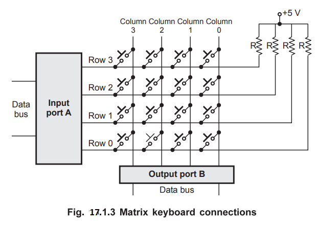
as shown in Fig. 18.1.1. Fig. 18.1.3 shows the interfacing of matrix keyboard.
It requires two ports : an input port and an output port. Rows are connected to
the input port referred to as returned lines, and columns are connected to the
output port referred to as scan lines. We know that, when all keys bus are
open, row and column do not have
any connection. When any key is pressed it shorts corresponding row and column.
If the output line of this column is low, it makes corresponding row line low;
otherwise the status of row line is high. The key is identified by data sent on
the output port and input code received from the input port. The following
section explains the steps required to identify pressed key.
Check
1 :
Whether any key is pressed or not
1.
Make all column lines zero by sending low on all output lines. This activates
all keys is in the keyboard matrix. (Note : When scan lines are logic high, the
status on the return lines do not change, it will remain logic high.)
2.
Read the status of return lines. If the status of all lines is logic high, key
is not pressed; otherwise key is pressed.
Check
2 :
1.
Activate keys from any one column by making any one column line zero.
2.
Read the status of return lines. The zero on any return line indicates key is
pressed from the corresponding row and selected column. If the status of all
lines is logic high, key is not pressed from that column.
3.
Activate the keys from the next column and repeat 2 and 3 for all columns.
We
will see how matrix keyboard can be connected to the 8051, a single chip
microprocessor/microcontroller. Fig. 17.1.4 shows the 4×4 matrix keyboard
connected to the port 1 of 8051. 4 lines of port 1 (P14-P17) are used as a scan
lines and remaining 4 lines (P10-P13) are used as return lines.

The
steps in algorithm are as follows :
1.
Initialise P1.0, P1.1, P1.2, P1.3 as inputs i.e. write '1' to these pins.
2. Check if all the keys are released by
writing 'O' to P1.4-P1.7 and check if all return lines are in state '1'. If No
then wait.
If
Yes then go to step 3.
3.
Call debounce.
4.
Wait for key closure. Ground all scan lines by writing 'O' and then check if at
least one of return lines shows '0' level.
Key
pressed ? No step 4
Yes
step 5
5.
Call debounce, (allow sufficient time for debounce)
6.
Is key really pressed ? (Ground all scan lines by writing '0' and then check if
at least one of the return lines shows '0' level.)
No
step 4
Yes
step 7
7.
Find key code and display the key pressed on 7-segment display.
(By
grounding one scan line at a time and checking return lines for any one line to
go to '0' level. )
8.
Go to step 1.
Program
:
org
lookup_table address
db
30h, 31h, 32h, 33h, 34h, 35h, 36h, 37h, 38h, 39h, 41h, 42h, 43h, 44h, 45h, 46h
org
program start address
beg: mov P1 #0f h ; configure lower 4 lines of
port 1 as i/p
mov
dptr,#lookup_table_address ; initialise dptr with
;
lookup_table_addr.
aga:
mov a, P1 ;
anl
a, #0fh ;
cjne
a, #0fh,aga ; check for key released
1call
delay ; call delay routine for key
debounce
agal: mov a, P1
anl
a, #0fh
cjne
a,#0fh, go ; check for key pressed
Ijmp
agal
go:
Icall delay ; call delay routine for key debounce
mov
a, P1
an1
a, #0fh
cjne
a,#0fh, go1 ; is key really pressed ?
Ijmp
agal
gol:
mov r1, # 01h ; initialise counter 1
mov
r0, #0efh ; store word for column selection
mov
r3, #04h ; initialise column counter
aga3: mov P1, r0 ; select only 1 column
mov
a, P1 ; get the status of return lines
jnb
acc.0,display ; check bit 0 and if it is 0 jump to display
inc
dptr ; increment lookup_table pointer
jnb
acc.1,display ; check bit 1 and if it is 1 jump to display
inc
dptr ; increment lookup_table pointer
inb
acc.2,display ; check bit 2 and if it is 2 jump to display
inc
dptr ; increment lookup_table pointer
jnb
acc.3,display ; check bit 3 and if it is 3 jump to display
inc
dptr ; increment lookup_table pointer
mov
a, r0 ; get the word for column selection
rl
a ; select next column
mov
r0, a ; store word for column selection
djnz
r3, aga3 ; check for last column
1jmp
beg ; if any key is not pressed scan again
end
Review Questions
1. With a neat circuit
diagram explain how a 4×4 keypad is interfaced with 8051 microcontroller
2. Interface an 8×8
keyboard using 8255 ports and write a program to read the code of a pressed
key. AU : Dec.-10, Marks 8
3. How do you
interface a 4 × 4 matrix keyboard using 8051 microcontroller ? AU : Dec.-11, Marks 8
4. How to interface a
4×4 matrix keyboard
using 8051 microcontroller and explain how to identify AU : Dec.-12,
Marks 8
5. Show how to interface a 8 × 8 matrix keyboard to the 8051 microcontroller and discuss in detail the various stages for detection and identification cf key activation by a microcontroller. Also, write an assembly language program to detect and identify the pressed key. AU : Dec.-19, Marks 15
Microprocessors and Microcontrollers: Unit V: (a) Microcontroller Applications : Tag: : Simple and Matrix - Keyboard Interface