Electric Circuit Analysis: Chapter - 1: Basic Circuit Analysis - DC
Kirchhoff's Laws
Statement, Formula, Solved Example Problems
The sum of the currents flowing towards a junction is equal to the sum of the currents flowing away from it.
KIRCHHOFF'S LAWS
Kirchhoff's
Current Law (I Law)
Statement
The
sum of the currents flowing towards a junction is equal to the sum of the
currents flowing away from it.
In
figure 1.15, A is a junction (or node) formed by six conductors. The currents
in these conductors are I1, I2 , ... I6. Some
of these currents are flowing towards A and others flowing away from it.
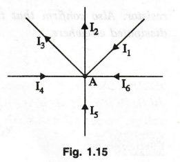
According
to Kirchhoff's Law,
I1
+ I4 + I5 + I6 = I2 + I3 ………
25)
(flowing
towards A) = (flowing away from A)
Kirchhoff's
Voltage Law (II Law)
Statement
In
a closed circuit, the sum of the potential drops is equal to the sum of the
potential rises.
In
figure 1.16, ABCDA form a closed circuit. Assuming the current direction as
shown, from A to B, we have a potential drop of IR1 volts. Writing
for the entire loop ABCDA, we have,
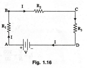
Sum
of potential drops = IR1 + IR2 + IR3
Potential
rise from D to A = V
IR1+
IR2 + IR3 = V
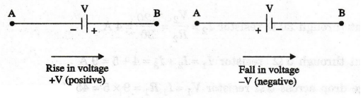
Sign
of EMFs
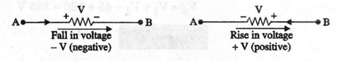
Sign
of Voltage Drops
EXAMPLE
56:
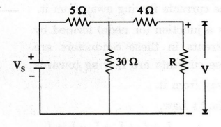
The power supplied to the load R and the voltage across it in figure are 500
W and 100 V. Determine (i) the value of the V, (ii) the power dissipated in
each resistor. Also confirm that the power delivered by the source equals the
total power dissipated elsewhere.
Solution
The
current and voltages are marked as shown in figure.

Power
delivered by the source = Power dissipated in all resistors
= 1485 W
EXAMPLE
57:
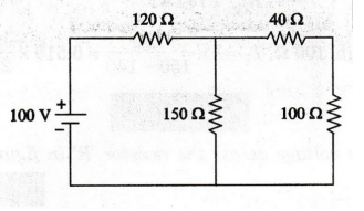
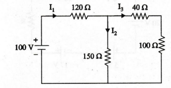
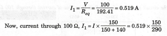
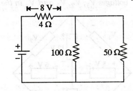
In the circuit shown in figure, find the value of current through 100 Ω.
Solution
The
current directions are marked as shown in the figure.
First,
find the equivalent resistance of the circuit. vode add
40 and 100 Ω are connected in series, .. 40 + 100 = 140 Ω
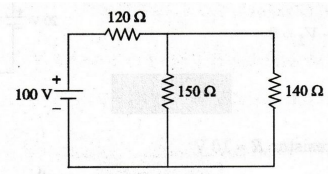 150
150
Ω and 140 Ω are connected in parallel.
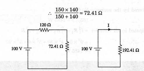
120
Ω and 72.41 Ω are connected in series, 120+ 72.41 = 192.41 Ω
I3
= 0.268 A
EXAMPLE
58: Find the voltage across the resistor
'R' in figure.
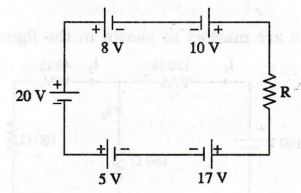
Solution
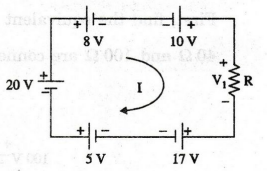
Applying KVL in the above circuit
20
- 8 + 10 - V1- 17 + 5 = 0
10
- V1 = 0
V1
= 10 V
Voltage
across the resistor R = 10 V
EXAMPLE
59:
Find the current through 12 2 resistor in figure. (AU/Mech - Dec 2004) -
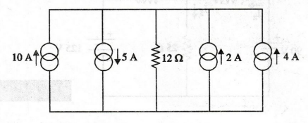
Solution:
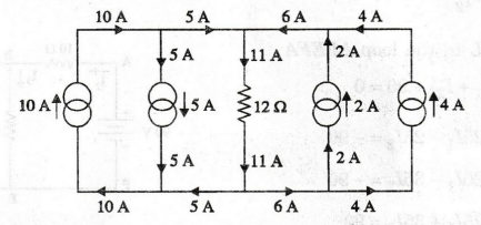
Here,
incoming current is 5+ 6 = 11 A
This
11 A current flows through the 12Ω resistor.
EXAMPLE
60:
For the circuit shown in figure, determine the unknown voltage drop V1
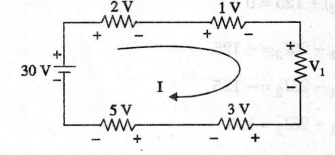
Solution:
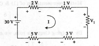
Applying
KVL in the above circuit
-2
– 1 - V1 – 3 – 5 + 30 = 0
-
V1+ 19 = 0
-
V1 = -19
V1
= 19 V
EXAMPLE
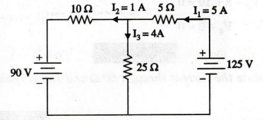
61:
Calculate the currents supplied by the two batteries in the network shown
in figure.
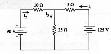
Solution:

Here,
negative sign indicates, the current direction is anticlockwise. It is shown in
figure.
I3
= I1 – I2 = 5 - 1 = 4A
The
current supplied by the battery 125 V is 5 A.
The
90 V battery is getting the charging current of 1A.
EXAMPLE
62:
Determine the voltages V1, V2, V3
and V4 in the circuit in figure given below.
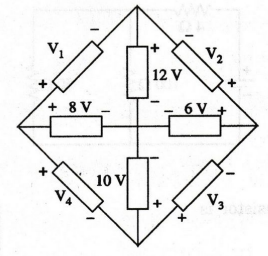
Solution
By
applying KVL in loop ABEA
-V1
- 12 + 8 = 0
-V1
– 4 = 0
-V1
= – 4 V
Consider
another loop BCEB
V2
– 6 + 12 = 0
V2
+ 6 = 0
V2
= - 6V
Consider
the loop CDEC
V3
– 10 + 6 = 0
V3
– 4 = 0
V3
= 4 V
Consider
the loop DAED
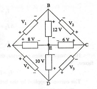
V4
- 8 + 10 = 0
V4
+ 2 = 0
V2
= -2 V
EXAMPLE
63:
Calculate the current through 50 and 100 22 resistors of circuit shown in
figure.
Solution
Current
through 4 Ω resistor is
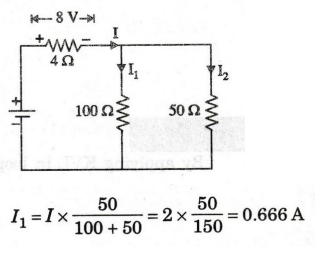
I1
= 0.666 A
I2
= I × 100 / 150 = 2 × 100 / 150
I2
= 1.333 A
EXAMPLE
64:
In the circuit of figure find using "Kirchhoff's Laws" the
currents in the various elements. Find also the power delivered by the battery.
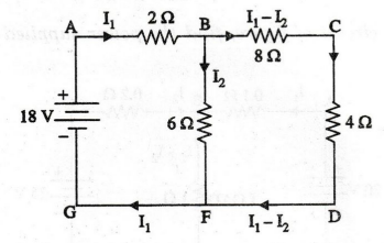
Solution
The
currents are marked in the circuit shown. In marking the currents, Kirchhoff's
current law is applied at all possible nodes. For instance, at node B, the
current I1 splits into I2 through the 62 resistor and
(11-12) through the 82 resistor. There are two unknown currents I1
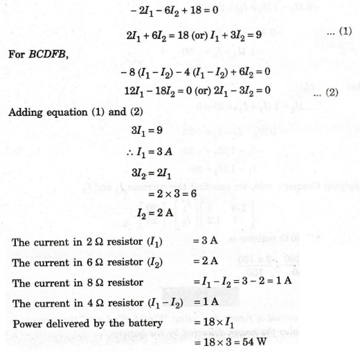
and I2. Closed loop equations are written for two loops. Considering
ABFGA,
EXAMPLE
65:
In the circuit of figure, find the power supplied to the load. Also find the
voltage at the load.
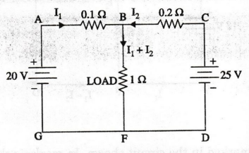
Solution
:
The
currents are marked using Kirchhoff's law. We write two closed loop equations
using Kirchhoff's second law and then solve for the two unknowns.
For
loop ABFGA
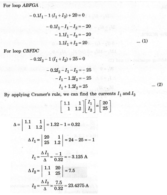
The
negative sign for I1 implies that current flows from B to A rather
than from A to B. This means that the current in the load is 20.3125 A.
(23.4375 -3.125)
Voltage
across the load = 20.3125 × 1 = 20.3125 V
Load
power = 12 × R = 20.31252 × 1 = 412.598 W
EXAMPLE
66:
In the circuit of figure, it is given that the current in the branch OA is
zero. Find the value of R and the current in it.
Solution
:
We
have marked the current in BA as I1 and BO as I2. Since there is no current in
OA, I1 flows through R (AC) and I2 through OC. There are
three unknowns R, I1 and I2. To solve these we need to
write three closed loop equations.
For
BOCB,
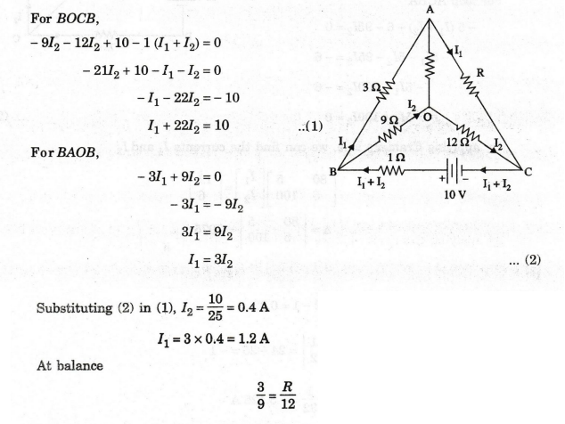
\R = 4 Ω
EXAMPLE
67:
In the circuit of figure, A is a milliammeter of resistance 5 Q. Find the
direction and magnitude of the current through it.
Solution:
The
currents are marked as in figure. Note that Kirchhoffs voltage law is applied
to loops. We write two loop equations and solve for the two unknowns I1
and I2.
For
loop ACDA

EXAMPLE
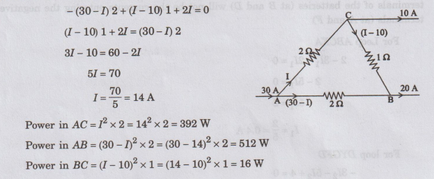
68:
In the circuit of figure, find the power dissipated in the individual resistors.
Solutios
:
The
currents are marked in figure. Since there is only one unknown, we write one
equation for the closed loop ABCA.
EXAMPLE
69:
In the Wheatstone bridge circuit of figure, G is a galvanometer of
resistance 102 Find the current through it.
Solution
:
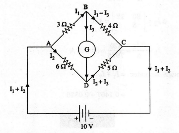
The
currents are marked as in figure. Kirchhoff's voltage law is applied to the various
loops. There are three unknowns I1, I2 , I3.
For
loop ABDA
-3I1
+ 6I2 -10I3 = 0
…. (1)
For
loop BDCB
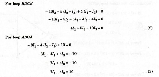
By
applying Cramer's rule we can can find the current 13 (Current through
galvanometer).
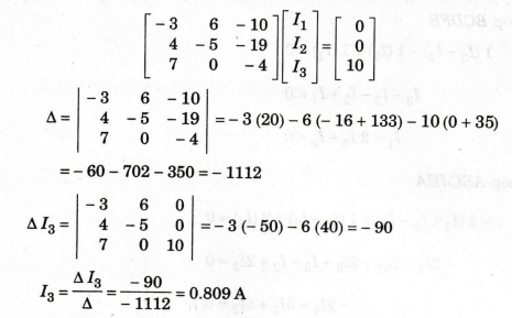
Current
through the galvanometer = 0.0809 A
EXAMPLE 70: In the circuit of figure, find the current through RL.
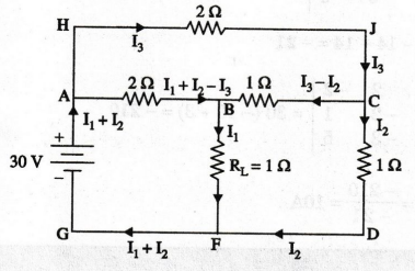
Solution
:
The
currents are marked as shown in figure. Applying Kirchhoff's voltage law, loop
equations are written for three closed circuits,
For
loop ABFGA
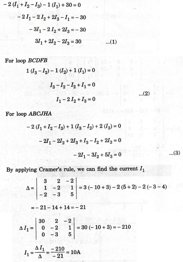
Current
through load resistor RL = 10 A
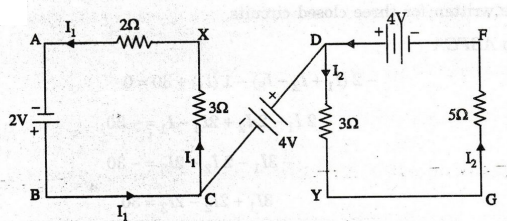
EXAMPLE
71:
What is the difference in potential between points X and Y in the circuit at
is the a shown in figure.
Solution
:
So
The currents in the loops ABCX and DYGF are marked as shown. There can be no
current in the branch CD as otherwise the currents coming out of the positive
terminals of the batteries (at B and D) will not be the currents entering the
negative terminals (at A and F)
For
Loop ABCXA
Therefore,
VXY = 1.2 + 4 - 1.5 (since VDY is a drop)
=
3.7 V (rise from X to Y)
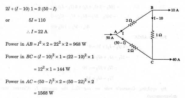
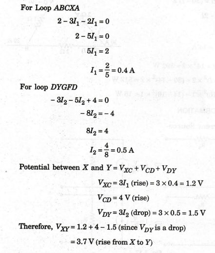
EXAMPLE
72:
Find the power dissipated in each resistor in the circuit shown in figure.
Solution:
The
currents are marked in figure. Since there is only one unknown, we write one
equation for the closed loop ABCA.
Electric Circuit Analysis: Chapter - 1: Basic Circuit Analysis - DC : Tag: : Statement, Formula, Solved Example Problems - Kirchhoff's Laws