Electric Circuit Analysis: Unit I: b. Basic circuits analysis
Kirchoff's laws
Definition, Principle, Explanation | Current and Voltage Law
Kirchoff's laws help us to solve the electrical networks. There are two laws which are stated as below.
KIRCHOFF'S
LAWS
Kirchoff's
laws help us to solve the electrical networks. There are two laws which are
stated as below.
1. Kirchoff's current law (Point law or first law)
It
states that, "the algebraic sum of the currents meeting at a junction
(node) is equal to zero."
Explanation:
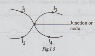
Let
the currents I1, I2, I3 and I4 flow
through the conductors meeting at a junction as shown. Take the currents
flowing towards the junction as positive and those flowing away from junction
as negative.
Then,
according to the above statement,
I1
+ I2 - I3 - I4 = 0
⇒ I1 + I2
= I3 + I4
i.e.,
At a junction, the sum of incoming currents = The sum of outgoing currents.
This is other way of stating the Kirchoff's law.
Note:
In
case of A.C. circuits, Kirchoff's current law, states that the phasor sum of
incoming currents is equal to the phasor sum of outgoing currents.
2. Kirchoff's Voltage Law: (Second law or mesh law)
"The
algebraic sum of electromotive forces plus the algebraic sum of voltages across
the impedances, in any closed electrical circuit is equal to zero."
Mathematically,
Σ emf + Σ IZ =0, in any closed electrical circuit.
The
reader may notice that we have to take algebraic sum of electromotive forces
and algebraic sum of voltages across impedances. It may be either positive or
negative. The following rules determine the sign for electromotive force and
also for voltage drop across impedance.
To determine the sign of
electromotive force
Let
us traverse round the loop in a clockwise direction. If we reach negative
terminal first and then positive terminal, that voltage is called voltage rise.
If we reach first positive terminal and then negative terminal, it is called
voltage fall.
Voltage
rise is given positive sign and voltage fall is given negative sign. The reader
need not try to know at present what voltage rise is and voltage fall. He can
remember the following rule.
While
traversing round a closed circuit, if he leaves a voltage source at positive,
it must be given positive sign. If he leaves the voltage source at negative, it
must be given negative sign.
For
this, the polarity of the leaving terminal is important.
To determine the sign of voltage
across the impedance
If
the direction of current through an impedance and direction of traversing round
the loop are same, the voltage drop is taken as negative.
If
the direction of current through the impedance is opposite to that of
traversing round the loop, then the voltage across the impedance is taken as
positive.
Note:
1.Till
the reader gets familiarity, he is advised to follow the above rule for sign
convention.
2.In
the statements given for the Kirchoff's laws, the right side of the equation is
zero.
3.
We can traverse round the circuit in anti-clockwise direction also, for
applying KVL. Even for that, the determination of sign can be as stated above.
4.
The determination of sign may be given in various ways. The reader is advised
not to get confusion. He can proceed confidently in one method.
5.
In these methods, the directions of currents for different branches can be
given by random. Then, the laws are applied to get the equations.
6.
On solving the equations, if all currents are found to be positive values, then
given directions are correct. If a particular current is found to be negative,
the direction of that current alone will be reversed. There is no change of
magnitude.
Explanation:
Consider the circuit shown in the figure.
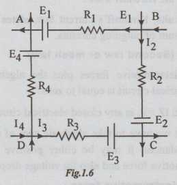
ABCDA
is one of the closed paths of the given circuit. AB, BC, CD and DA are the
branches. We assume that I1, I2, I3 and I4
are the branch currents. The directions of these currents are given by random,
independent of the polarities of the source.
At
the nodes A, B, C and D there are some more live conductors.
Let
us apply KVL for the loop ABCDA. We start from A, go clockwise and come back to
A at last. We know that,
Σ
emf + Σ IR = 0
Applying
sign convention, we get
Σ
emf = -E1 + E2 + E3 + E4
Σ
IR =I1 R1 - I2 R2 - I3 R3
- I4 R4
Therefore,
the equation becomes,
(-E1
+ E2 + E3 + E4 ) + (I1 R1
- I2 R2 - I3 R3 - I4
R4) = 0 ... (i)
Note:
(i) If we traverse in the anticlockwise direction, for
the loop ADCBA. Applying KVL, we get,
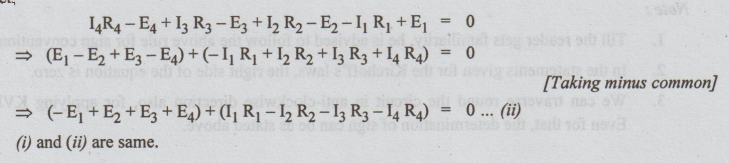
i.e.,
We can state that whether the circuit is traversed round either clockwise or
anti-clockwise, we get the same equation.
2.
The student should not traverse in one direction, say clockwise to determine
the sign of emf and another direction anti-clockwise to determine the sign of
IR, for any particular closed path.
Methods of solving electrical
network by Branch Current Method
Step 1:
Identify the nodes or junctions and hence the branches. Assume the direction of
current in a branch randomly.
Step 2:
Apply KCL at the nodes.
Step 3: Apply
KVL for the closed paths.
Step 4: Write
the equations.
Step 5: Obtain
the unknown currents by solving the equations.
Electric Circuit Analysis: Unit I: b. Basic circuits analysis : Tag: : Definition, Principle, Explanation | Current and Voltage Law - Kirchoff's laws
Related Topics
Related Subjects

Electric Circuit Analysis
EE3251 2nd Semester 2021 Regulation | 2nd Semester EEE Dept 2021 Regulation