Electron Devices and Circuits: Unit I: PN Junction Devices
LED
Symbols, Operation working principle, Construction, Biasing, Advantages, Disadvantages, Comparison, Applications, Solved Example Problem
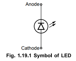
• The LED is an optical diode, which emits light when forward biased. The Fig. 1.19.1 shows the symbol of LED which is similar to p-n junction diode apart from the two arrows indicating that the device emits the light energy.
LED
AU
: Dec.-09, 11, 17
•
The LED is an optical diode, which emits light when forward biased. The Fig.
1.19.1 shows the symbol of LED which is similar to p-n junction diode apart
from the two arrows indicating that the device emits the light energy.
1. Basic Operation
•
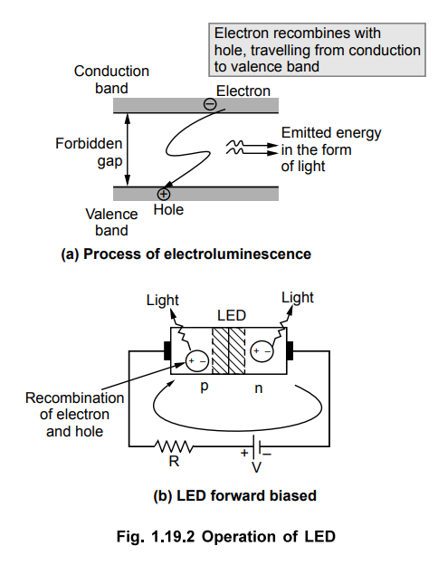
Whenever a p-n junction is forward biased, the electrons cross the p-n junction
from the n-type semiconductor material and recombine with the holes in the
p-type semiconductor material. The free electrons are in the conduction band
while the holes are present in the valence band. Thus the free electrons are at
higher energy level with respect to the holes. When a free electron recombines
with hole, it falls from conduction band to a valence band. Thus the energy
level associated with it changes from higher value to lower value. The energy
corresponding to the difference between higher level and lower level is
released by an electron while travelling from the conduction band to the
valence band. In normal diodes, this energy released is in the form of heat.
But LED is made up of some special material which release this energy in the
form of photons which emit the light energy. Hence such diodes are called light
emitting diodes.
•
This process is called electroluminescence.
•
The Fig. 1.19.2 shows the basic principle of this process. The energy released
in the form of light depends on the energy corresponding to the forbbiden gap.
This determines the wavelength of the emitted light. The wavelength determines
the colour of the light and also determines whether the light is visible or
invisible (infrared). The various impurities are added during the doping
process to control the wavelength and colour of the emitted light. For normal
silicon diode, the forbidden energy gap is 1.1 eV and wavelength of the emitted
light energy corresponds to that of infrared light spectrum hence in normal
diodes the light is not visible. The infrared light is not visible.
2. Materials and Colours
•
The LEDs use mixtures of Gallium (Ga), Arsenic (As) and Phosphorous (P).
•
The colour of emitted light is decided by its wavelength which depends on
forbidden energy gap. This gap is different for different mixtures. Hence
different mixtures give the different colours.

3. Construction of LED
•
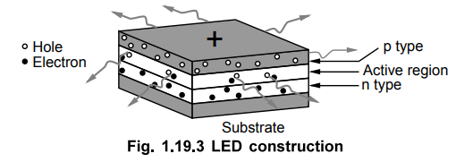
One of the methods used for the LED construction is to deposite three
semiconductor layers on the substrate as shown in the Fig. 1.19.3. In between p
type and n type, there exists an active region. This active region emits light,
when an electron and hole recombine. When the diode is forward biased, holes
from p type and electrons from n type, both get driven into the active region.
And when recombine, the light is emitted.
•
In this particular structure, the LED emit light all the way around the layered
structure. Thus the basic layered structure is placed in a tiny reflective cup
so that the light from the active layer will be reflected towards the desired exit
direction.
4. Biasing of LED
•
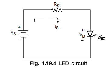
Consider a source connected to LED and a resistor as shown in the Fig. 1.19.4.
•
The outward arrows associated with a diode indicate that it is LED.
•
The resistor RS is the current limiting resistor. Due to this
resistor, the current through the circuit is limited and prevented from
exceeding the maximum current rating of the diode.
•
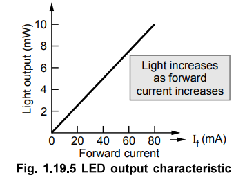
When forward biased, as forward current increases, the light output also
increases. The graph of output light in mW against forward current If in mA is
shown in the Fig. 1.19.5.
•
When forward biased, the voltage drop across conducting LED is about 2 to 3 V
which is considerably greater than that across a normal silicon or germanium
diode. The current range of commercially available LEDs is 10 to 80 mA. Unless and
otherwise specified, while analyzing the LED circuits, the drop across LED is
considered as VD = 2V.
•
The reverse breakdown voltage of LED is much less than the normal diode, which
is about 3 V to 10 V.
5. Advantages of LED
•
The various advantages of LED are,
1.
LEDs are small in size, and hence can be regarded as point source of light.
Because of their small size, several thousand LEDs can be packed in one sq.
metre area.
2.
The brightness of light emitted by LED depends on the current flowing through
LED. Hence the brightness of light can be smoothly controlled by varying the
current. This makes possible to operate LED displays under different ambient
lighting conditions.
3.
LEDs are fast operating devices. They can be turned on and off in time less
than 1 microsecond.
4.
The LEDs are light in weight.
5.
The LEDs are available in various colours.
6.
The LEDs have long life.
7.
The LEDs are cheap and readily available.
8.
The LEDs are easy to interface with various other electronic circuits.
9.
Some LEDs radiate infrared light which is invisible but still useful in some
applications like burglar alarm systems.
10.
LEDs are useful for the applications which are subjected to frequent on-off
cycling. The fluorescent lamps bum out more quickly when cycled.
11.
LEDs can be easily dimmed using pulse width modulation or by controlling the
forward current.
12.
LEDs are shock resistant and difficult to damage due to external shocks.
13.
LEDs do not contain toxic material like mercury which is used in fluorescent
lamps.
6. Disadvantages of LED
•
The various disadvantages of LED are,
1.
It draws considerable current requiring frequent replacement of battery in low power
battery operated devices.
2.
Luminous efficiency of LED is low which is about 1. lumen/watt.
3.
The characteristics are affected by temperature.
4.
Need large power for the operation compared to normal p-n junction diode.
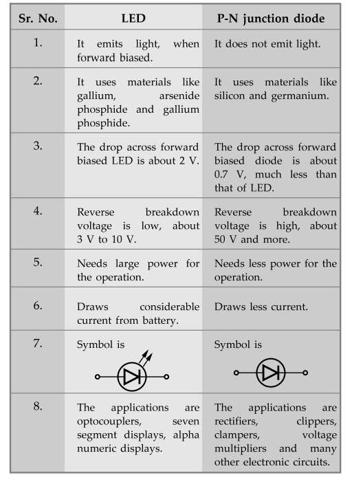
7. Comparison of LED and p-n junction Diode.
Ex. 1.19.1 What is the current through LED used in a circuit shown in the Fig. 1.19.6.
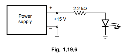
Sol. : Assume the drop across the LED as 2 V.
VD = 2V
From Fig. 1.19.6, Rg = 2.2 k Ω and VS = 15 V

Ex.
1.19.2 What value of series resistor is required to limit the current through a
LED to 20 mA with a forward voltage drop of 1.6 V when connected to a 10 V
supply? AU: Dec.-17, Marks 3
Sol.
:
VS
= 10 V, VD = 1.6 V,
IS
= 20 mA
IS
= VS – VD / RS
i.e.
20 × 10-3 = 10-1.6 / RS
Rs
= 420 Ω ... Series resistor
8. Applications of LED
•
Due to the advantages like low voltage, long life, cheap, reliable, fast on-off
switching etc., the LEDs used in many applications. The The various
applications of LED are,
1.
All kinds of visual displays i.e. seven segment displays and alpha numeric
displays. Such displays are commonly used in the watches and calculators.
2.
In the optical devices such as optocouplers.
3.
As on-off indicator in various types of electronic circuits.
4.
Some LEDs radiate infrared light which is invisible. But such LEDs are useful
in remote controls and applications like burglar alarm.
Review Question
1. Discuss the working principle, construction, characteristics
and applications of LED in detail. AU : Dec.-09, 11, 17,
Marks 8
Review Question
1. Discuss the working principle, construction, characteristics and applications of LED in detail. AU : Dec.-09, 11, 17, Marks 8
Electron Devices and Circuits: Unit I: PN Junction Devices : Tag: : Symbols, Operation working principle, Construction, Biasing, Advantages, Disadvantages, Comparison, Applications, Solved Example Problem - LED
Related Topics
Related Subjects

Electron Devices and Circuits
EC3301 3rd Semester EEE Dept | 2021 Regulation | 3rd Semester EEE Dept 2021 Regulation