Linear Integrated Circuits: Unit V: Application ICs
LM 380 Power Audio Amplifier
Operating working principle, Features, Pin Diagram, Symbol, Internal circuit diagram, Applications
LM 380 is a popular power audio amplifier produced by National Semiconductor. It is capable of delivering 2.5 W(r.m.s) minimum to 8 Q load. Hence it is very much ideal for consumer applications.
LM 380 Power Audio Amplifier
LM
380 is a popular power audio amplifier produced by National Semiconductor. It
is capable of delivering 2.5 W(r.m.s) minimum to 8 Q load. Hence it is very
much ideal for consumer applications. It requires minimum number of external
components. In order to keep the cost to a minimum, its gain is internally
fixed to 50 i.e. 34 dB.
1. Features of LM 380 Audio Amplifier
The
LM 380 audio amplifier has following features :
1.
Internally fixed gain (34 dB).
2.
Wide supply voltage range (5 to 22 V).
3.
Output is automatically self centreing to one half of the supply voltage.
4.
Output is short circuit proof with internal thermal limiting.
5.
A unique input stage allows input to be ground referenced or a.c. coupled.
6.
Low quiescent power drain.
7.
High peak current capability (1.3 A maximum).
8.
High input impedance (150 kΩ).
9.
Low total harmonic distortion, THD (0.2 %).
10.
Standard dual in line package.
11.
A bandwidth of 100 kHz typically at an output power of 2 W and load of 8 Ω.
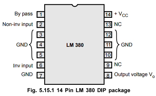
2. Pin Diagram of LM 380
The
Fig. 5.15.1 shows the pin diagram of LM 380 power audio amplifier. A copper
lead frame is used with the centre three pins on either side (3, 4, 5, 10, 11
and 12) of the DIP package comprises a heat sink. Hence there is no need to use
a separate external heat sink for the audio amplifier.
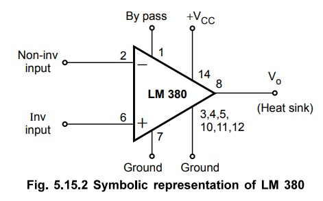
Symbolically
LM 380 audio amplifier is represented as shown in the Fig. 5.15.2.
3. internal circuit diagram of LM 380
The
LM 380 audio power amplifier consists of four stages
1.
PNP emitter follower
2.
Darlington compound differential amplifier
3.
Common emitter
4.
Quasi-Complementary emitter follower.
The
internal circuit diagram is shown in the Fig. 5.15.3.
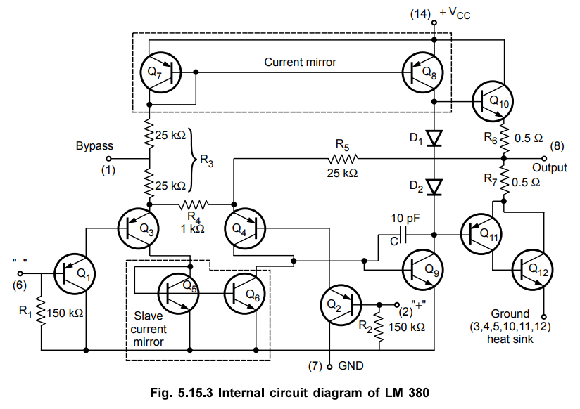
The
PNP transistors Q1 and Q2 form an emitter follower input
stage. This drives PNP Q3 -Q4, the differential
amplifier. Because of PNP transistors the input can be referenced to ground
i.e. the input can be direct coupled to either inverting (6) or non-inverting
(2) terminals of the amplifier. The differential amplifier is biased by R3
and R5.
The
current in the PNP differential pair Q3 - Q4 is decided
by the Q7, R3 and + VCC. The current mirror of
Q7 and Q8 and the associated resistors then establishes
current through collector of Q 9. The transistors Q5 - Q6 acts
as active load for the PNP differential pair.
The
output of the differential pair is taken at the junction of Q4 and Q6
and is applied as an input to the common emitter voltage gain stage.
The
transistor Q9 with diodes D1 and D2 form the
common emitter voltage gain stage where Q8 acts as a current source load. The
capacitor is a feedback capacitor and is used for the frequency compensation to
stabilise the amplifier against any type of oscillations. It also establishes
the upper cut-off frequency off 100 kHz at 2 W for 8 Ω loads. The diodes D1
and D2 are used to develop a small prebias voltage across the base
emitter junctions of Q10 and Q11, so as to minimize the
cross over distortion. The resistances R6 and R7 are used
for current limiting.
The
output stage is a quasi-complementary pair emitter follower using NPN
transistors Q10 and Q12. The quiescent output voltage
level is centered at approximately one half the supply voltage by resistor
ratio R3 and R5. This allows the maximum peak to peak
output voltage swing and therefore maximum a.c. output voltage.
The
resistances R1 and R2 provide a d.c. return path for the
input bias current so that the amplifier can be operated with either input
terminal open.
To
decouple the input stage from the supply voltage +VCC, a bypass capacitor
of the order of microfarads should be connected between the bypass terminal (1)
and the ground (7). The pins 3, 4, 5, 10, 11, 12 are ground heat sink pins.
The
overall internal voltage gain of the amplifier is fixed at 50.
4. Applications of LM 380 Audio Amplifier
As
the number of external components required for LM 380 is very less, it is
mostly used for consumer applications. Some of such applications are discussed
below.
a.
LM 380 as Audio Power Amplifier
The
simplest and most basic application of LM 380 is as an audio power amplifier.
The IC can be used in inverting as well as non-inverting configuration. When
used in the non-inverting mode the inverting terminal can be either shorted to
ground, left open or returned to ground through resistor or capacitor.
Similarly, when it is used in the inverting configuration, the non-inverting
terminal may be either shorted to ground or returned to ground through resistor
or capacitor. In both the configurations, the supply voltage must be decoupled
by connecting a capacitor between the terminal 14 and ground. As a
precautionary measure a lag compensating RC network must be connected at the
output to ground, to eliminate 5 to 10 MHz oscillations. The LM 380 as audio
power amplifier in non-inverting mode is shown in the Fig. 5.15.4.

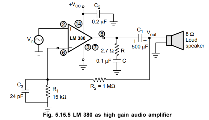
b.
LM 380 as High Gain Audio Amplifier
As
mentioned earlier, LM 380 is a fixed gain audio amplifier whose gain is
internally fixed to 50 (34 dB). But with the help of positive feedback its gain
can be increased upto 300. The Fig. 5.15.5 shows the use of LM 380 as an audio
amplifier with gain 200, using positive feedback.
c.
LM 380 with a Variable Gain
The
circuits discussed above are the amplifiers designed for fixed gain values. But
variable gain upto 50 can be obtained with the use of a potentiometer across
the two input terminals. This is shown in the Fig. 5.15.6.
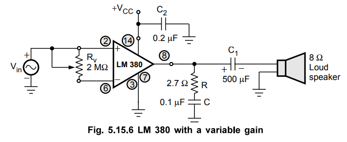
This
circuit can be used for volume control.
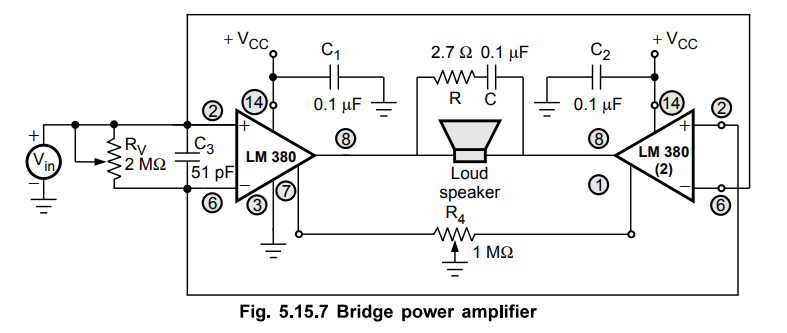
d.
Bridge Configuration using LM 380
If
the load requires more power than a single LM 380 can deliver, the bridge
amplifier using LM 380 can be used. The bridge power amplifier uses two LM 380
ICs. The bridge amplifier provides the maximum output voltage swing twice as
that provided by single LM 380 amplifier. Due to this the power delivered to
the load is four times that delivered by single LM 380 amplifier. Fig. 5.15.7
shows the bridge power amplifier using LM 380 ICs. The resistance R4
is used to balance the output offset voltages of LM 380 ICs.
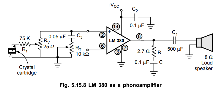
e.
Phono Amplifier using LM 380
A
phono amplifier with volume and tone control can be obtained using LM 380. The
output is given to the 8 Ω loud speaker. The resistances R (2.7 Ω) and C (0.1 µF)
are used for circuit stability from the undesirable oscillations.
The
port Kv is used for the volume control with a pot of 25 k Ω while
the port KT is used for the tune control with a pot of 10 k Ω. The
phonoamplifier using LM 380 is shown in the Fig. 5.15.8. The crystal cartridge
is used at the input side.
f.
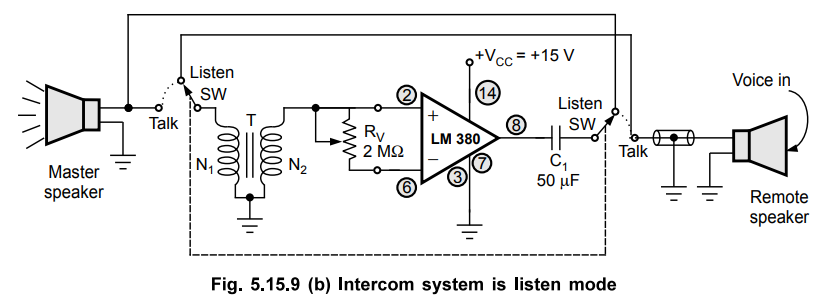
Intercom System using LM 380
Fig.
5.15.9. (a) shows the intercom system using LM 380, in talk mode.
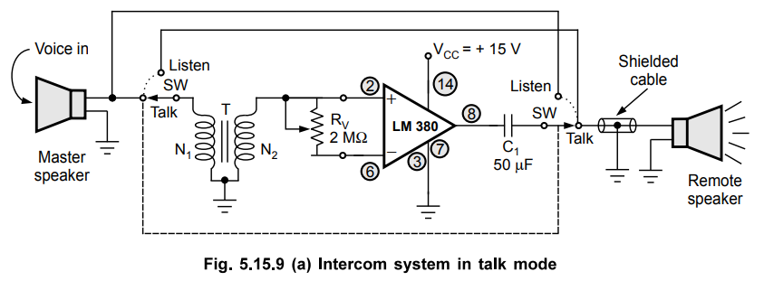
The
speakers used are of permanent magnet type and hence they act as microphones
also. Depending upon the role of the master speaker action, the system can be
operated in talk mode or listen mode.
When
the switch SW is in talk mode, the master speaker acts as microphone accepting
the voice in, with the help of step up transformer T. The overall gain of the
circuit is constant and depends on the turns ratio of the transformer T as well
as internal gain of LM 380. But generally the internal gain of LM 380 is kept
controllable with the help of pot at Rv port as shown.
When
the switch SW is in listen state, the circuit acts in listen mode as shown in
the Fig. 5.15.9 (b). The roles of remote speaker and the master speaker get
interchanged.
g.
Siren / Alarm using LM 380 Power Amplifier
The
certain conditions may be monitored by blowing siren or alarm in a complex
system. The undesirable conditions can be recognised by producing variety of
sounds using sirens or burglar alarms.
Such
a siren or alarm system can be designed using following basic components :
i)
Audio amplifier LM 380
ii)
Dual op-amp MC 1458
iii)
1 W speaker.
The
dual op-amp is to be used as a signal generator which can generate triangular,
square or pulse waveform. While the IC LM 380 is used as an audio amplifier
which is discussed earlier. The entire siren or alarm system is shown in the
Fig. 5.15.10.
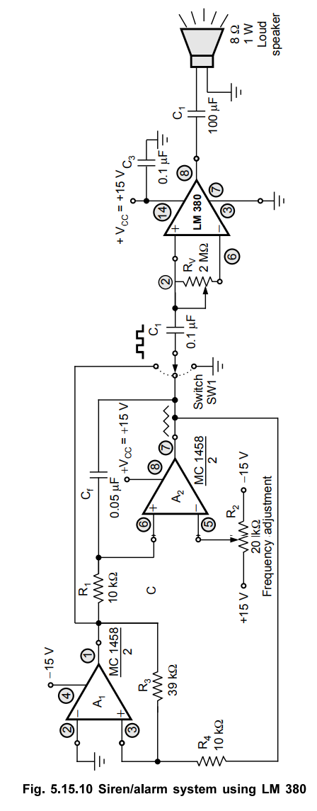
The
MC 1458 is dual op-amp consisting op-amps A1 and A2. Both
together composed of a wave form generator. The output of A1 is a square wave
while output of A2 is triangular or sawtooth waveform. The
potentiometer R 2 not only controls the frequency but also decides the type of
the output waveform of A1 and A2. The switch SW1 connects the
outputs of A1 and A2 to the LM 380 audio amplifier. Only
one output at a time, either of A1 or A 2 gets connected
to LM 380 with the help of switch SW1. The LM 380 drives the 8Ω , 1 W
loudspeaker. A pot Rv connected at the input terminals of LM 380
controls the sound level. The sound level depends on the switch position, R2
position and capacitor Cf. So varying sound intensities can be
obtained.
Instead of op-amp signal generator, the waveform generator using 555 also can be used.
Review Questions
1. Draw the internal circuit schematic of LM 380 power amplifier
and briefly discuss its salient features.
2. What are features of LM 380 power amplifier ? With a
schematic, explain its application as high gain audio power amplifier.
3. With necessary diagrams, explain the applications of LM 380
IC.
May-08, Dec.-15, Marks 10
4. Write a note on LM380 power amplifier.
Linear Integrated Circuits: Unit V: Application ICs : Tag: : Operating working principle, Features, Pin Diagram, Symbol, Internal circuit diagram, Applications - LM 380 Power Audio Amplifier
Related Topics
Related Subjects

Linear Integrated Circuits
EE3402 Lic Operational Amplifiers 4th Semester EEE Dept | 2021 Regulation | 4th Semester EEE Dept 2021 Regulation