Electrical Machines: Unit II: D.C. Generators
Load Characteristics of D.C. Compound Generator
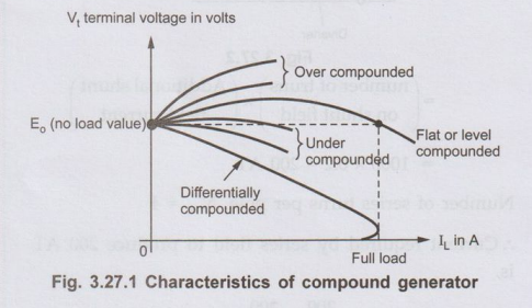
If drop in Vt, due to increasing IL is more dominating than increase in Vt due to increase in flux then generator is called under compounded and its characteristics is dropping in nature, as shown in the Fig. 3.27.1.
Load
Characteristics of D.C. Compound Generator
AU May-07, 12, 15, Dec.-03, 09, 10,
15
• The characteristics depends on whether
generator is cumulatively compound or differentially compound generator. In
cumulatively compound, ϕT = ϕsh + ϕse. As load
current increases, Ia increases hence Ise also increases
producing more flux. Thus induced e.m.f. increases and terminal voltage also
increases. But as Ia increases, the various voltage drops and
armature reaction drop also increases. Hence there is drop in the terminal
voltage.
If
drop in Vt, due to increasing IL is more dominating than
increase in Vt due to increase in flux then generator is called
under compounded and its characteristics is dropping in nature, as shown in the
Fig. 3.27.1.
•
If drop in Vt due to armature reaction and other drops is much less
than increase in Vt due to increase in flux then generator is called
over compounded and its characteristics is rising in nature, as shown in the
Fig. 3.27.1. If the effects of the two are such that on full load current Vt
is same as no load induced e.m.f. i.e. the effects are neutralising each other
on full load then generator is called flat compounded or level compounded. Its
characteristics is shown in the Fig. 3.27.1.
•
In differentially compound, ϕT =
ϕsh ~ ϕse. The net flux is difference between the
two. As IL increases, ϕsh is almost constant but ϕse
increases rapidly. Hence the resultant flux ϕT reduces. Hence the
induced e.m.f. E and hence the terminal voltage also decreases drastically.
There is drop due to armature resistance, series field resistance, armature
reaction due to which terminal voltage drops further. Thus we get the
characteristics of such differentially compound generator as shown in the Fig.
3.27.1.
Ex. 3.27.1
A long shunt compound generator has a
hunt field winding of 1,000 turns per pole and series eld winding of 4 turns
per pole and a resistance of .05 Ω. In order to obtain the same voltage both at
load nd full load for operating as shunt generator, it is ecessary to increase
the field current by 0.2 A. The full ad armature current of the compound
generator is 0 A. Calculate the diverter resistance connected in arallel of
series field to obtain flat compound operation?
AU: Dec.-15, Marks 8
The
generator is shown in the Fig. 3.27.2.
Ia
= 80 A
Addiotional
ampere-turns required to maintain rated voltage on full load for operation as a
shunt generator.
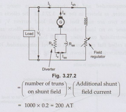
(number
or truns om shunt fileld) × (Additional shunt field current)
=
1000 × 0.2 = 200 AT
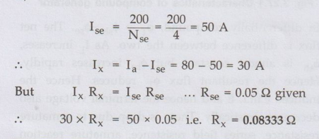
Number
of series turns per pole, Nse = 4
..
Current required by series field to produce 200 AT is,
Review Questions
1. Draw and explain
load characteristics of d.c. compound generator.
AU May-07, 15,
Dec.-10, 15, Marks 8
2. Draw the
performance characteristics of different types of different types of d.c.
generators and explain them.
AU: Dec.-03, 09,
May-12, Marks 8
Electrical Machines: Unit II: D.C. Generators : Tag: : - Load Characteristics of D.C. Compound Generator
Related Topics
Related Subjects

Electrical Machines I
EE3303 EM 1 3rd Semester EEE Dept | 2021 Regulation | 3rd Semester EEE Dept 2021 Regulation