Electrical Machines II: UNIT III: b. Circle Diagram
Load Test on Three Phase Induction Motor
The induction motor is loaded by any of the following methods : 1. Brake test 2. By connecting a d.c. generator
Load Test on Three Phase Induction Motor
By
conducting the load test on three phase induction motor, the performance of the
motor viz. slip, power factor, input, efficiency etc. at various loads can be
studied.
The
induction motor is loaded by any of the following methods :
1.
Brake test
2.
By connecting a d.c. generator
In
case of loading by connecting a d.c. generator, the induction motor is
connected to a d.c. generator. The generator is loaded by a lamp bank. Thus
inturn an induction motor is loaded. The Fig. 6.7.1
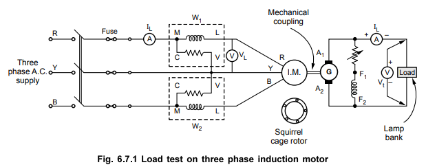
shows
the experimental set up for conducting load test on three phase induction motor
using a d.c. generator.
On
induction motor side, ammeter reads line current IL and voltmeter reads line
voltage VL. The two wattmeters are connected as per the two wattmeter method
hence,
Pin
= Power input = W1+ W2
On
generator side, the ammeter reads load current IL and voltmeter
reads terminal voltage Vt
By
varying the lamp bank, load on generator i.e. load on induction motor can be
varied. The induction motor can be star or delta connected and can be squirrel
cage or slip ring type. The speed readings are taken using tachometer. The load
is increases till induction motor carries rated line current. The following
observation table is prepared,

Calculations
:
The output of induction motor is input to a d.c. generator.
Output
of d.c. generator = Vt × IL W
Assume ƞgen = 80 %
Pout
of induction motor = of d.c. generator
=
Pout of d.c. generator / ƞgen = VtIL / ƞgen W
Pin
of induction motor = W1 + W2 W

For
various loads above parameters are obtained.
As
the load on the induction motor increases,
1.
The output of motor increases.
2.
The power factor increases.
3.
The efficiency increases upto certain load and then decreases.
4.
The speed decreases marginally.
5.
The slip increases.
6.
The input current increases.
The
various performance characteristics can be obtained as shown in the Fig. 6.7.2.
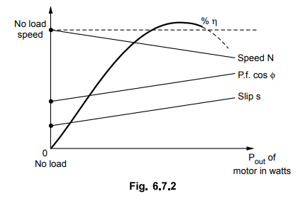
The
graphs indicate the behaviour of various performance parameters against output
of the induction motor and not shown to the scale.
Review Question
1. How do conduct load test on an induction motor ? How the
various parameters of induction motor change as the load changes ?
Electrical Machines II: UNIT III: b. Circle Diagram : Tag: Engineering Electrical Machines - II : - Load Test on Three Phase Induction Motor
Related Topics
Related Subjects

Electrical Machines II
EE3405 Machine 2 EM 2 4th Semester EEE Dept | 2021 Regulation | 4th Semester EEE Dept 2021 Regulation