Transmission and Distribution: Unit II: (a) Modelling and Performance of Transmission Lines
Long Transmission Lines
In the analysis of short and medium lines we were assuming that the capacitance associated with the line is lumped or concentrated at one or more point although in actual practice it is distributed along the length of line.
Long Transmission Lines
In the analysis of short and medium
lines we were assuming that the capacitance associated with the line is lumped
or concentrated at one or more point although in actual practice it is
distributed along the length of line. If same assumption is made for the
analysis of long transmission line then it is seen that serious errors occur in
its performance parameters. Thus for better accuracy, the line constants in
case of long transmission line are considered to be uniformly distributed
throughout the length of line. Rigorous mathematical treatment is to be made
for obtaining the solution in case of such lines.
The equivalent circuit of a 3 phase long
transmission line is shown in the Fig. 2.10.1. For simplicity only one phase is
shown. The entire length of the transmission line is divided into n sections
with each section having the line constants 1/n times that for total line.
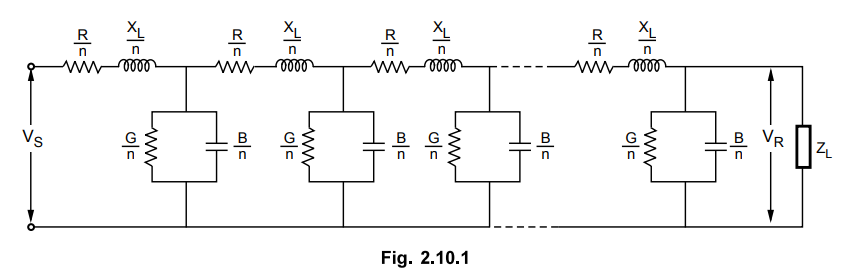
The resistance and the inductive reactance forms the series elements whereas the leakage susceptance (B) and leakage conductance (G) forms shunt elements. Because of the capacitance existing between line and neutral the leakage susceptance is present. The leakage taking place over the conductors or due to corona effect between the conductors forms leakage conductance. The leakage current through shunt admittance is maximum at the sending end and decreases continuously towards the receiving end.
Transmission and Distribution: Unit II: (a) Modelling and Performance of Transmission Lines : Tag: : - Long Transmission Lines
Related Topics
Related Subjects

Transmission and Distribution
EE3401 TD 4th Semester EEE Dept | 2021 Regulation | 4th Semester EEE Dept 2021 Regulation