Electric Circuit Analysis: Unit I: b. Basic circuits analysis
Loop (mesh) current method
Definition, Circuit Diagram, Solving Steps, Equation
In the loop current method, we need to write (and solve) equations for as many currents as the number of independent loops. The number of independent loops is equal to (b − n + 1).
LOOP (MESH) CURRENT METHOD
In
the loop current method, we need to write (and solve) equations for as many
currents as the number of independent loops. The number of independent loops is
equal to (b − n + 1).
This
is based on Kirchoff's voltage law and applicable to only planar networks. Here
KCL is applied automatically. In this method the loop current is an independent
variable. The number of loop current equations is equal to number of independent
loops.
Consider
the network shown below. For convenience numerical are not given.
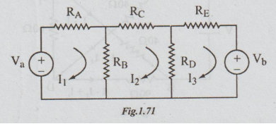
In
the network given, there are three nodes (junctions) i.e., n = 3. The branches
are five i.e., b = 5. If/= number of independent loops, l = b – n + 1 = 5 – 3 +
1 = 3.
Therefore,
there will be three independent loop equations.
Assume,
the loop currents to be I1, I2 andI3 as shown
in the figure, all clockwise.
Each
loop current is confined to that particular loop only. The currents through RA,
RC, RE are I1, I2, I3
respectively.
The
current through RB is I1 - I2, and through RD
is I2 - I3. Applying KVL to the left loop, we get

It
is usual to write these equations in terms of self and mutual resistances
(impedances). The self resistance of a loop is the sum of the resistances
encountered in a traverse of that loop. Thus for the circuit drawn,
the
self resistance of loop 1 = R11 = RA + RB
the
self resistance of loop 2 = R2 = RB+ RC + RD
the
self resistance of loop 3 = R33 = RD + RE
The
resistance which is common to more than one loop is called mutual resistance.
Denoting the mutual resistance between loop 1 and loop 2 by R12 and
so on.
R12 = R21 = RB
R23
= R32 = RD
Introducing
these in the set of loop equations (1), (2) & (3).
R11I1
- R12I2 = Va...(4)
-R21
I1 - R22 I2 - R23 I3 = Va
....(5)
And
-
R32 I2 + R33 I3 =- Vb ....(6)
It
should be noted that all the terms representing mutual resistances have a
negative sign. This can be avoided by putting R12 = R21 -
RB.
Finally
the general form of loop equations for the given circuit containing three
independent loops will be
R11
I1 + R12 I2 + R13 I3 = Va
...(7)
R21
I1 + R22 I2 + R23 I3 = 0
...(8)
R31
I1 + R32 I2 + R33 I3 = Vb
...(9)
Writing
equations (7), (8), (9) in the matrix form, we get
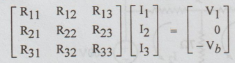
In
general the above matrix form is expressed as below:
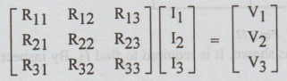
The
last general form is to be remembered well for solving the problems.
Here,
V1= the algebraic sum of the e.m.f. in the loop 1.
V2
= the algebraic sum of the e.m.f. in the loop 2.
Similarly,
V3 = the algebraic sum of the e.m.f. in loop 3. An e.m.f. is
assigned positive if the loop current leaves at positive terminal of the
source. For example, in loop 1, V1 =+ Va. I3
leaves Vь at negative terminal. So, V3 = - Vb.
[Note:
1.
If directions of loop currents are not given assume all of them to be clockwise
blindly. After solving, if a particular loop current is found to be negative,
reverse only the direction of that loop current.
2.
The self resistances are always taken as positive.
3.
The mutual resistance is positive if the current through it is the sum of two
loop currents.
4. The mutual resistance is negative if the
current through it is the difference of two loop currents.
5.
From the matrix, we can find the various loop currents by using determinants.
Remember,
I1
= Δ1/Δ ,I2 = Δ2 /Δ ,I3 = Δ3/Δ
The
students will commit mistakes generally by taking I1 = Δ/Δ1
,I2 = Δ/Δ2 and so on.
6.
Loop current method can also be used for AC circuits. There, you have to
replace R by Z.
7.
If the network consists of practical current source it is convenient to convert
it into practical voltage source, for loop current analysis.
Electric Circuit Analysis: Unit I: b. Basic circuits analysis : Tag: : Definition, Circuit Diagram, Solving Steps, Equation - Loop (mesh) current method
Related Topics
Related Subjects

Electric Circuit Analysis
EE3251 2nd Semester 2021 Regulation | 2nd Semester EEE Dept 2021 Regulation