Electrical Machines II: UNIT I: b. Armature Reaction and Regulation of Alternators
M.M.F. Method of Determining Regulation
Synchronous Generator or Alternators
This method of determining the regulation of an alternator is also called Ampere-turn method or Rothert's M.M.F. method.
M.M.F. Method of Determining Regulation AU
: May-13, 17,18, Dec.-15, 16, 17
This
method of determining the regulation of an alternator is also called
Ampere-turn method or Rothert's M.M.F. method. The method is based on
the results of open circuit test and short circuit test on an alternator.
For
any synchronous generator i.e. alternator, it requires M.M.F. which is product
of field current and turns of field winding for two separate purposes.
1.
It must have an M.M.F. necessary to induce the rated terminal voltage on open
circuit.
2.
It must have an M.M.F. equal and opposite to that of armature reaction m.m.f.
Key
Point : In most of the cases as number of turns on the
field winding is not known, the M.M.F. is calculated and expressed in terms of
the field current itself.
The
field M.M.F. required to induce the rated terminal voltage on open circuit can
be obtained from open circuit test results and open circuit characteristics.
This is denoted as FO
We
know that the synchronous impedance has two components, armature resistance and
synchronous reactance. Now synchronous reactance also has two components,
armature leakage reactance and armature reaction reactance. In short circuit
test, field M.M.F. is necessary to overcome drop across armature resistance and
leakage reactance and also to overcome effect of armature reaction. But drop
across armature resistance and leakage reactance is very small and can be
neglected. Thus in short circuit test, field M.M.F. circulates the full load
current balancing the armature reaction effect. The value of ampere-turns
required to circulate full load current can be obtained from short circuit
characteristics. This is denoted as FAR.
Under
short circuit condition as resistance and leakage reactance of armature do not
play any significant role, the armature reaction reactance is dominating and
hence the power factor of such purely reactive circuit is zero lagging. Hence
F^ gives demagnetising ampere turns. Thus the field M.M.F. is entirely used to
overcome the armature reaction which is wholly demagnetising in nature.
The
two components of total field M.M.F. which are Fo and F, Circuit
Characteristics) and S.C.C. (Short Circuit Characteristics) as shown in the
Fig. 2.14.1.

If
the alternator is supplying full load, then total field M.M.F. is the vector
sum ofits two components FO and FAR- This depends on the power
factor of the load which alternator is supplying. The resultant field M.M.F. is
denoted as FR. Let us consider the various power factors and the resultant FR.
Zero
lagging p.f. : As long as the power factor is zero
lagging, the armature reaction is completely demagnetising. Hence the resultant
FR is the algebraic sum of the two components FO and FAR.
Field M.M.F. is not only required to produce rated terminal voltage but also
required to overcome completely demagnetising armature reaction effect.
This
is shown in the Fig. 2.14.2.

OA
= Fo
AB
= FAR Demagnetising
OB
= FR = FO + FAR
Total
field M.M.F. is greater than FO.
Zero
leading p.f. : When the power factor is zero leading
then the armature reaction is totally magnetising and helps main flux to induce
rated terminal voltage. Hence net field M.M.F. required is less than that
required to induce rated voltage normally, as part of its function is done by
magnetising armature reaction component. The net field M.M.F. is the algebraic
difference between the two components FO and FAR. This is
shown in the Fig. 2.14.3
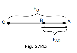
OA
= FO
AB
= FAR Magnetising
OB
= FO - FAR = FR
Total
M.M.F. is less than FO
Unity
p.f. : Under unity power factor condition, the armature
reaction is cross magnetising and its effect is to distort the main flux. Thus
FO and F^ are at right angles to each other and hence resultant
M.M.F. is the vector sum of FO and FAR. This is shown in
the Fig. 2.14.4.

OA
= FO
AB
= FAR Cross magnetising

General
Case : Now consider that the load power factor is cos . In
such case, the resultant M.M.F. is to be determined by vector addition of FO
and FAR.
Cos
ϕ , lagging p.f. : When the load p.f. is cos lagging, the
phase current Iaph lags Vph by angle . The component FO is at right
angles to Vph while FAR is in phase with the current Iaph.
This is because the armature current Iaph decides the armature reaction. The
armature reaction FAR due to current Iaph is to be overcome by field M.M.F.
Hence while finding resultant field M.M. F-/ - FAR should be added
to FO vectorially. This is because resultant field M.M.F. tries to
counterbalance armature reaction to produce rated terminal voltage. The phasor
diagram is shown in the Fig. 2.14.5.

From
the phasor diagram the various magnitudes are,
OA
= FO,
AB
= FAR' OB = FR
Consider
triangle OCB which is right angle triangle. The FAR is split into
two parts as,
AC
= FAR
sin
ϕ and BC = FAR cos ϕ
(FR)2
= (FO + FAR sin ϕ)2 + (FAR cos ϕ)2
… (2.14.1)
From
this relation (2.14.1), FR can be determined.
Cos
ϕ J leading p.f. : When the load p.f. is cos ϕ leading, the
phase current Iaph leads Vph by ϕ • The component FO
is at right angles to Vph and FAR
is in phase with Iaph. The resultant FAR can be obtained
by adding - FAR to FO. The phasor diagram is shown in the
Fig. 2.14.6.

From
the phasor diagram, various magnitudes are,
AC
= FAR sin ϕ and
BC
= FAR COS ϕ
OA
= FO, AB = FAR and OB = FR
Consider
triangle OCB which is right angle triangle.
(OB)2
= (OC)2 + (BC)2
(FR)2
= (Fo - FAR sin ϕ) 2 + (FAR cos ϕ)2 …(2.14.2)
From
the relation (2.14.2), FR can be obtained.
Using
relations (2.14.1) and (2.14.2), resultant field M.M.F. FR for any
p.f. load condition can be obtained.
Once
FR is known, obtain corresponding voltage which is induced e.m.f. Eph,
required to get rated terminal voltage Vph. This is possible from
open circuit characteristics drawn.
Once
Eph is known then the regulation can be obtained as,
%
Reg. = Eph - Vph / Vph × 100

Note
:
To obtain Eph corresponding to FR, O.C.C. must be drawn
to the scale, from the open circuit test readings.
Key Point : This ampere-turn
method gives the regulation of an alternator which is lower than that actually
observed. Hence the method is called optimistic method.
Important
note : When the armature resistance is neglected then Fo
is field m.m.f. required to produce rated Vph at the output
terminals. But if the effective armature resistance Raph is given
then Fo is to be calculated from O.C.C. such that Fo represents the excitation
(field current) required to produce a voltage of Vph + Iaph
Ra cos ϕ
where Vph = Rated voltage per
phase
Iaph
= Full load current per phase
Ra
= Armature resistance per phase
cos
ϕ = Power factor of the load
It
can also be noted that, FR can be obtained using the cosine rule to
the triangle formed by FO, FAR and FO as shown
in the Fig. 2.14.8.

Using
cosine rule to triangle OAB,
(FR)2
= (FO) 2 + (FAR) 2 - 2 FO
FAR COS (FO Λ FAR)
FO
Λ FAR = 90 + ϕ if ϕ is lagging
=
90 - ϕ if is leading
Students
can use equations (2.14.1), (2.14.2) or (2.14.3) to calculate FR.
The
angle between EO and Vph is denoted as 8 and is called power
angle.
Neglecting
Ra we can write,
IaXs
cos ϕ = EO sin δ
Pd
= VphIa cos ϕ = Internal power of machine
Pd
= Vph ( EO / XS ) sin δ
Key
Point This equation shows that the internal power of the
machine is proportional to sin δ.
Example
2.14.1 The open and short circuit test readings for a 3
phase star connected, 1000 kVA, 2000 V, 50 Hz synchronous generator are
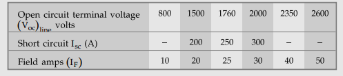
The
armature effective resistance is 0.2 Ω per phase. Draw the characteristics
curves and estimate full load percentage regulation (a) 0.8 p.f. lagging (b)
0.8 p.f. leading. Use M.M.F. method. AU : May-17, Dec.-15,
Marks 16
Solution
:
While sketching O.C.C., convert the given line values to phase by dividing each
value by √3. This is because the alternator is star connected. The
characteristics are shown in Fig. 2.14.11.
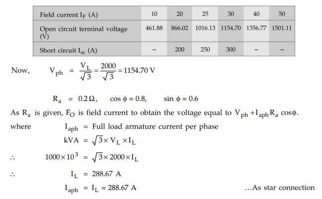
Vph
+ Iph Ra cos ϕ = 1154.70 + (288.67) (0.2) (0.8) = 1200.8872 volts
Find
FO corresponding to voltage of 1200.88 V from O.C.C
So
FO = 32.5 A
While
FAR is field current required to circulate full load short circuit current of
288.67 so obtain it from S.C.C.
FAR
- 29.5 A
For
lagging power factor the phasor diagram is shown in Fig. 2.14.9.

From
triangle OCB,
(FR)2
- (FO + FAR sin ϕ)2 + (FAR cos ϕ)2
=
(32.5 + 29.5 × 0.6)2 + (29.5 × 0.8)2 = (2520.04) +
(556.96)
=
3077
FR
= 55.47 A
Now
obtain Eph corresponding to FR = 55.47 A of field current
from O.C.C. For FR = 55.47, Eph = 1560 V from graph shown
in the Fig. 2.14.11.

For
0.8 p.f. leading, FR can be obtained as follows,
cos
ϕ = 0.8, ϕ = 36.86°

90
- ϕ = 90 - 36.86 = 53.14°
Using
cosine rule to triangle OAB

Example
2.14.2 A 1.1 MVA, 2.2 kV, 3 phase, star - connected
alternator gave the following test result during OC and SC tests :

The
effective resistance of the 3 - phase winding is 0.22 Ω /ph. Estimate the full
- load voltage regulation at 0.8 pf. lagging.
i)
By Synchronous impedance method and ii) Ampere – turn method
Solution
:
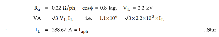
Plot
O.C.C. and S.C.C. on graph. Convert the open circuit voltage values to phase
values while sketching O.C.C., by dividing each value by √3 as alternator is
star connected. The graphs are shown in the Fig.2.14.12

i)
Synchronous impedance method

ii)
Ampere - turn method :
As
Ra is given, FO is the field current to obtain the
voltage equal to Vph + Iaph-Ra cos ϕ
Vph
+ Iaph Ra cos ϕ = 1270.17 + 288.67 × D.22 × 0.8 = 1320.97 V
From
O.C.C. in Fig .2.14.12, If corresponding
to 1320.97 V is FO = 32.5 A.
While
FAR is If required to circulate full load short circuit
current of 288.67 A i.e. FAR = 14 A
Consider
the phasor diagram for 0.8 lagging p.f. as shown in the Fig. 2.14.13. From the
Fig. 2.14.13,

(FR)2
= (FO + FARsin ϕ) 2 + (FAR cos ϕ) 2
= (32.5 + 14 × 0.6)2 + (14 × 0.8)2
FR
= 42.4 A
From
O.C.C. in the graph, Eph corresponding to FR = If
= 42.4 A is 1520 V.

Example
2.14.3 A 3.3 kV alternator gave the following results :
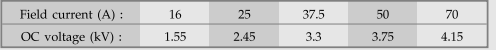
A
field current of 18 A is found to cause the full load current to flow through
the winding during short circuit test. Predetermine the full load voltage
regulation at (1) 0.8 pf lag and (2) 0.8 pf lead by MMF method. AU
: May-13, Marks 8
Solution
:
The field current required for producing rated terminal voltage of 3.3 kV is
37.5 A i.e. FO = 37.5 A. The field current required to circulate
full load current during short circuit is 18 A i.e. FAR = 18 A
Vph
= 3.3 kV / √3 = 1905.2558 V
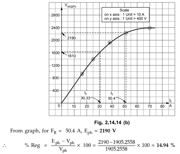
73
i)
cos ϕ = 0.8 lagging : The phasor diagram is shown in the Fig.
2.14.14 (a).

(FR)2
= (FO + FAR sin ϕ)2 + ( FAR cos ϕ)2
= (37.5 + 18 × 0.6)2 + (18 × 0.8)2
i.e.
FR
= 50.4 A
Alternative
method to obtain FR is to use consine rule to triangle OAB.
To
find Eph corresponding to FR, plot open circuit
characteristics to the scale from given table as shown in the Fig. 2.14.14 (b).
Note that phase values are obtained by dividing the given voltages by √3 and
are used to obtain the graph.
ii) cos ϕ = 0.8 leading
The
phasor diagram is shown in the Fig. 2.14.14(c).

Examples
for Practice
Example 2.14.4 The following test results are obtained on 6600 V, alternator,

A
field current of 20 A is found necessary to circulate full load current on
short circuit of the armature. Calculate by a) mmf method and b) The
synchronous impedance method, the full load regulation of 0.8 p.f. (lagging). Neglect
resistance and leakage reactance.
[Ans.:
- 21.27 %, -19.71 %]
Example 2.14.5 A 3 phase, 200 kVA, 1.1 kV, 50 Hz star connected alternator having an effective per phase resistance of 0.62 Ω, gave the following results

Using
MMF method, find the voltage regulation at 100 A, at a) 0.8 lagging and b) 0.8
leading p.f.
[Ans.:
104.38 % 73.205 %]
Example
2.14.6 A 1 MVA, 11 kV, 3- ϕ,
star connected synchronous machine has the following OCC test data,

where
EOL is line to line voltage at no load. The short circuit test
yielded full load current at a field current of 65 A, the armature resistance
is negligible, Calculate the voltage regulation at full load 0.866 p.f. lagging
by m.m.f. method.
[Ans.:
22.031 %]
Review Question
1. Explain M.M.F. method cf predeterming the regulation of
alternator.
Electrical Machines II: UNIT I: b. Armature Reaction and Regulation of Alternators : Tag: Engineering Electrical Machines - II : Synchronous Generator or Alternators - M.M.F. Method of Determining Regulation
Related Topics
Related Subjects

Electrical Machines II
EE3405 Machine 2 EM 2 4th Semester EEE Dept | 2021 Regulation | 4th Semester EEE Dept 2021 Regulation