Electrical Machines: Unit I: b. Electromechanical Energy Conversion
M.M.F. of Distributed A.C. Windings
It is seen that the armature winding used for three phase alternators is distributed in nature. The efforts are made to place the coils in all the slots available per pole per phase.
M.M.F. of
Distributed A.C. Windings
AU: May-14,17
•
It is seen that the armature winding used for three phase alternators is
distributed in nature. The efforts are made to place the coils in all the slots
available per pole per phase. Such coils are then interconnected such that the
magnetic field produced by armature after carrying current has same number of
poles as that of field winding. Let us obtain the m.m.f space distribution of
the current carrying armature by superimposing the m.m.f. space waves of
individual coils.
1. M.M.F. Space Wave of a Single Coil
•
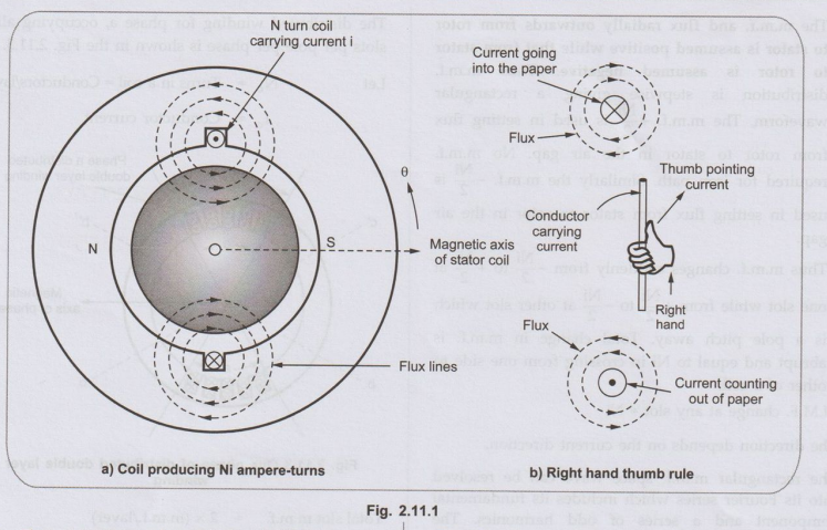
Consider single multiturn coil, carrying N turns and is a full pitch coil.
It carries a current i such that the total ampere turns produced by the coil is
(Ni). The direction of current i is as shown in the Fig. 2.11.1 and hence
direction of flux lines around a and a' can be obtained by using right hand
thumb rule.
•
The stator is wound for two poles same as the number of poles for which field
winding is wound. Due to the flux lines produced by the coil, the North and
South poles are induced on the stator periphery. The magnetic axis of the
stator coil is from N pole to S pole as shown in the Fig. 2.11.1 (a).
The assumptions to obtain M.M.F. space
wave are,
1.
It is cylindrical rotor machine.
2.
The armature and rotor are made up of high is grade magnetic material hence
permeability of these parts is much higher than air. Hence u reluctance is low
so entire reluctance can be assumed to be due to two air gaps.
3.
Thus if total m.m.f. is Ni then half the m.m.f. is required to creat flux from
rotor to stator in the air gap while half is required to create flux from
stator to rotor in the air gap.
•
The flux lines radially crosses the air gap between rotor and stator twice,
normal to the stator and rotor iron surfaces.
•
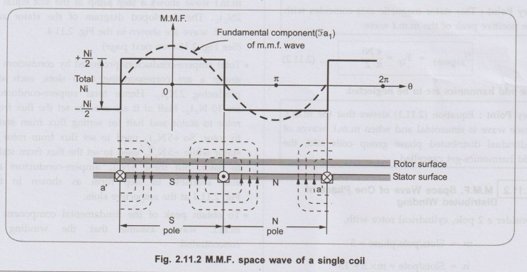
Consider a developed diagram of the coil shown in the Fig. 2.11.2 such that
rotor surface is over the stator which is laid down flat.
•
The m.m.f. and flux radially outwards from rotor to stator is assumed
positive while that from stator to rotor is assumed negative. Thus m.m.f.
distribution is stepwise giving a rectangular waveform. The m.m.f. + Ni/2 is
used in setting flux from rotor to stator in the air gap. No m.m.f. required
for iron path. Similarly the m.m.f. –Ni /2 is used in setting flux from stator
to rotor in the air gap.
•
Thus m.m.f. changes suddenly from -Ni / 2 to + Ni /2 at one slot while from
+Ni/2 to – Ni/2 at other slot which is a pole pitch away. Total change in
m.m.f. is abrupt and equal to Ni in crossing from one side to other of a coil.
M.M.F.
change at any slot = Ni
The
direction depends on the current direction.
The
rectangular m.m.f. space wave can be resolved into its Fourier series which
includes its fundamental component and a series of odd harmonics. The
fundamental component of m.m.f wave is given by,
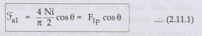
Where
θ = Electrical angle measured from stator magnetic axis.
Key
Point: This stator magnetic axis coincides with the
positive peak of the m.m.f wave.
The
odd harmonics are to be neglected.
Key
Point: Equation (2.11.1) shows that the m.m.f. space wave
is sinusoidal and when m.m.f. waves of individual distributed phase group coils
add, the odd harmonics get cancelled.
2 M.M.F. Space Wave of One Phase of Distributed Winding
Consider
a 2 pole, cylindrical rotor with,
m
= Slots/pole/phase = 5
n
= Slots/pole = m × 3 = 15
The
distributed winding for phase a, occupying all 5 slots per pole per phase is
shown in the Fig. 2.11.3.
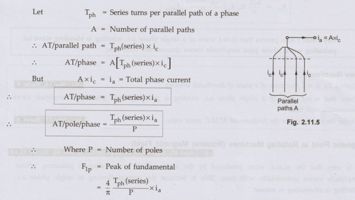
Let
Nc
= Tums in a coil = Conductors/layer
Ic
= Conductor current

Total
slot m.m.f. = 2 × (m.m.f./layer) ….. as double layer
=
2Ncic
•
As the number of slots are odd, half of ampere conductors of middle slot of a
and a' constitute S-pole and remaining half contribute N-pole. The m.m.f wave
shows a step jump at the slot equal to 2Ncic. The developed diagram of the
stator and m.m.f. wave are shown in the Fig. 2.11.4.
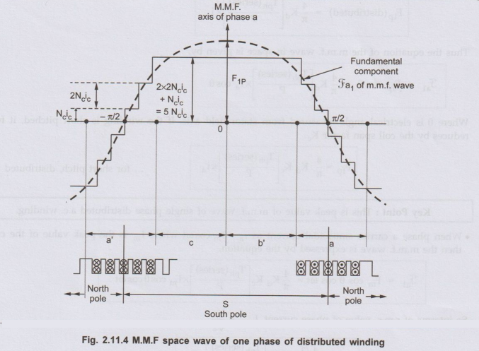
•
Total ampere-conductors produced by conductors of group a are corresponding to
5 slots, each slot producing 2Ncic. Hence total ampere-conductors are 10 Nic.
Half of it are used to set the flux from rotor to stator and half for setting
flux from stator to rotor. So +5 Neic used to set flux from rotor to stator
while -5Nei, used to set the flux from stator to rotor. But these 5Nic
ampere-conductors are also available in step form as shown in the Fig. 2.11.4
at the respective slots.
•
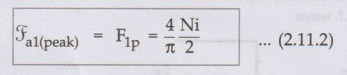
To obtain peak of the fundamental component of m.m.f. wave, assume that the
winding is concentrated.
•
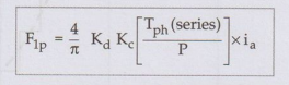
But this is peak if winding is concetrated. When winding is distributed, the
peak will be reduced by the distribution factor Kd.
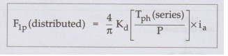
Thus
the equation of the m.m.f. wave in space is given by,
Where
θ is electrical angle measured from stator field axis. If the winding is short
pitched, it further reduces by the coil span factor Kc.
for
short pitch, distributed winding
Key Point:
This is peak value of m.m.f. wave of single phase distributed a.c. winding.
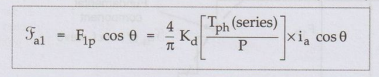
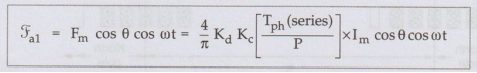
•
When phase a carries sinusoidal current as ia = Im cos wt
where Im is the peak value of the current then the m.m.f. wave is expressed by
the equation.
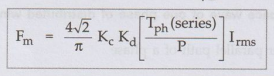
So
interms of r.m.s. value of phase current, Irms= Im/√2
Key Point:
This proves that m.m.f wave of a single phase a.c. winding is standing wave
i.e. pulsating wave whose peak amplitude varies sinusoidally with time.
Review Questions
1. Explain the m.m.f.
flux wave of a phase of distributed winding.
AU: May-14, Marks 8
2. Prove that m.m.f.
wave of a single phase a.c. winding is pulsating wave whose peak amplitude
varies sinusoidally with time.
3. Derive the
expression for the fundamental M.M.F. space wave.
AU: May-17, Marks 8
Electrical Machines: Unit I: b. Electromechanical Energy Conversion : Tag: : - M.M.F. of Distributed A.C. Windings
Related Topics
Related Subjects

Electrical Machines I
EE3303 EM 1 3rd Semester EEE Dept | 2021 Regulation | 3rd Semester EEE Dept 2021 Regulation