Electrical Machines: Unit I: a. Magnetic Circuits and Electromagnetism
Magnetic Circuits
The magnetic circuit can be defined as, the closed path traced by the magnetic lines of force i.e. flux. Such a magnetic circuit is associated with different magnetic quantities as m.m.f., flux reluctance, permeability etc.
Magnetic
Circuits
AU
: Dec.-02,10,11,13,17,18,19, May-11,13,14,19
• The magnetic circuit can be defined as, the
closed path traced by the magnetic lines of force i.e. flux. Such a magnetic
circuit is associated with different magnetic quantities as m.m.f., flux
reluctance, permeability etc.
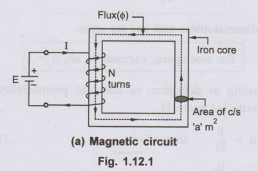
• Consider simple magnetic circuit shown in the Fig. 1.12.1 (a). This circuit consists of an iron core with cross-sectional area of 'a' m2 with a mean length of 'l' m. (This is mean length of the magnetic path which flux is going to trace.) A coil of N turns is wound on one of the sides of the square core which is excited by a supply. This supply drives a current I through the coil. This current carrying coil produces the flux (0) which completes its path through the core as shown in the Fig. 1.12.1 (a)
•
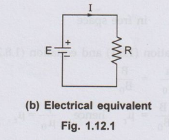
This is analogous to simple electric circuit in which a supply i.e. e.m.f. of E
volts drives a current I which completes its path through a closed conductor
having resistance R. This analogous electrical circuit is shown in the Fig.
1.12.1 (b).
Let
us derive relationship between m.m.f., flux and reluctance.
I
= Current flowing through the coil,
N
= Number of turns.
ϕ
= Flux in webers,
B
= Flux density in the core.
µ
= Absolute permeability of the magnetic material
µr = Relative permeability of the magnetic material
Magnetic field strength inside
the solenoid is given by,
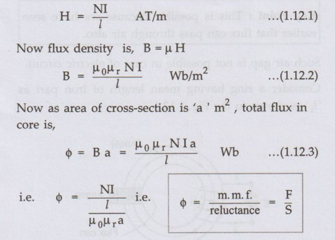
where
NI = Magnetomotive force m.m.f. in AT
S
= l/µ0 µra =
Reluctance offered by the magnetic path.
This
expression of the flux is very much similar to expression for current in
electric circuit.
I = e.m.f.
/resistance
Key Point :
So current is analogous to the flux, e.m.f. is analogous to the m.m.f. and
resistance is analogous to the reluctance.
Ex.
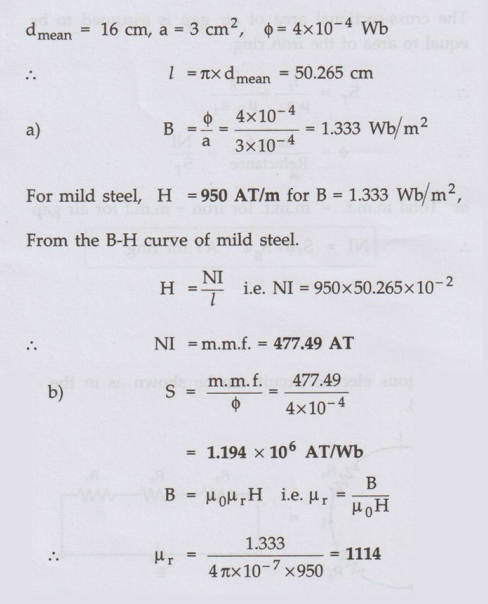
1.12.1 A toroidal core made of mild steel has a mean
diameter of 16 cm and a cross - sectional area of 3 cm2. Calculate a) the m.m.f
to produce a flux of 4x10⁻⁴ Wb and b) the corresponding values of the
reluctance of the core and the relative permeability. AU : Dec.-17, Marks 15
Sol. :
1. Series
Magnetic Circuits
•
In practice magnetic circuit may be composed of various materials of different
permeabilities, of different lengths and of different cross-sectional areas.
Such a circuit is called composite magnetic circuit. When such parts are
connected one after the other the circuit is called series magnetic circuit.
•
Consider a circular ring made up of different materials of lengths l1,
l2 and l3 and with cross-sectional areas a1, a2,
and a3 with absolute permeabilities µ1, µ2 and
µ3 as shown in the Fig. 1.12.2
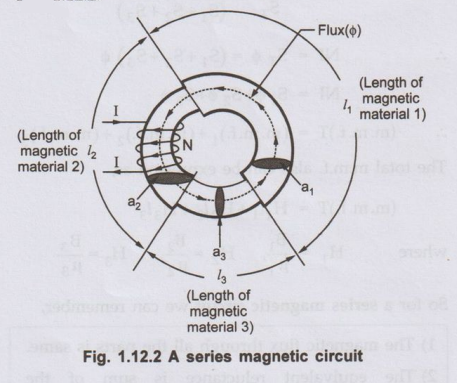
Let
coil wound on ring has N turns carrying a current of I amperes.
The
total m.m.f. available is = NI AT
This
will set the flux 'ϕ’ which is same through all the three elements of the
circuit.
This
is similar to three resistances connected in series in electrical circuit and
connected to e.m.f. carrying same current 'T' through all of them.
Its
analogous electric circuit can be shown as in the Fig. 1.12.3.
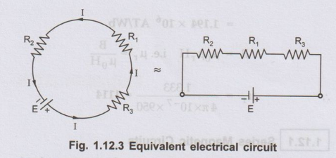
The
total resistance of the electric circuit is R1 + R2 + R3.
Similarly the total reluctance of the magnetic circuit is,
So
for a series magnetic circuit we can remember,
1)
The magnetic flux through all the parts is same.
2)
The equivalent reluctance is sum of the reluctance of different parts.
3)
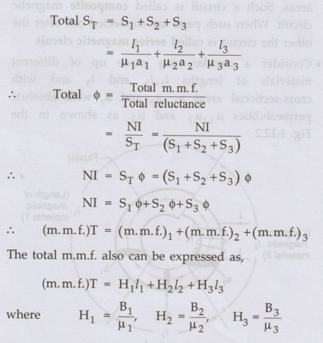
The resultant m.m.f. necessary is sum of the m.m.f.s in each individual part.
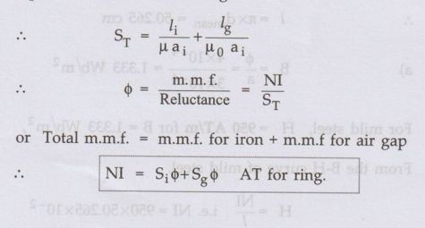
2. Series Circuit with Air Gap
•
The series magnetic circuit can also have a short air gap.
Key Point :
This is possible because we have seen earlier that flux can pass through air
also.
Such
air gap is not possible in case of electric circuit.
Consider
a ring having mean length of iron part as ' li' as shown in the Fig. 1.12.4.
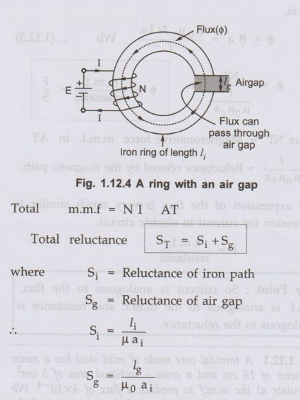
Key Point :
The absolute permeability of airma µ = µ0
The
cross-sectional area of air gap is assumed to be equal to area of the iron
ring.
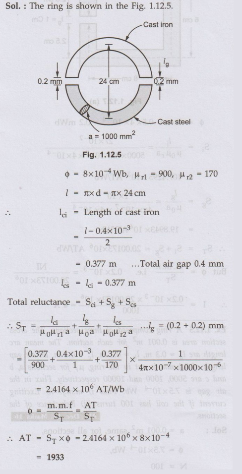
Ex 1.12.2
A ring has a diameter of 24 cm and a cross sectional area of 1000 mm . The ring
is made up of semicircular sections of cast iron and cast steel with each joint
having a reluctance equal to an air-gap of 0.2 mm. Find the ampere turns
required to produce a flux of 8x 10⁻⁴ Wb. The relative permeability
of cast-steel and cast-iron are 900 and 170 respectively. Neglect fringing and
leakage effects.
AU
: Dec.-18, Marks 13
Sol. :
The ring is shown in the Fig. 1.12.5.
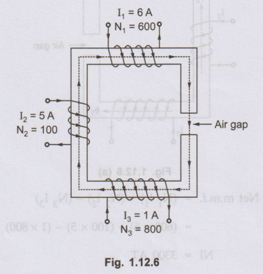
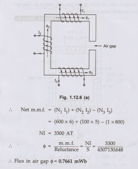
Ex. 1.12.3
A magnetic circuit is excited by three coils as shown in the Fig. 1.12.6.
Calculate the flux produced in the air gap. The material used for core is iron
having relative permeability of 800. The length of the magnetic circuit is 100
cm with an air gap of 2 mm in it. The core has uniform cross-section of 6 cm2.
AU : Dec.-02, Marks 8
Sol.
: Given,
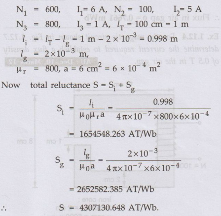
Let
us find the direction of flux due to various coils using right hand thumb
rule.
As
shown in the Fig. 1.12.6 (a) m.m.f. of coil (1) and (2) are in same direction
while m.m.f. of coil (3) is in opposite direction.
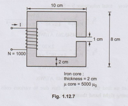
Ex.
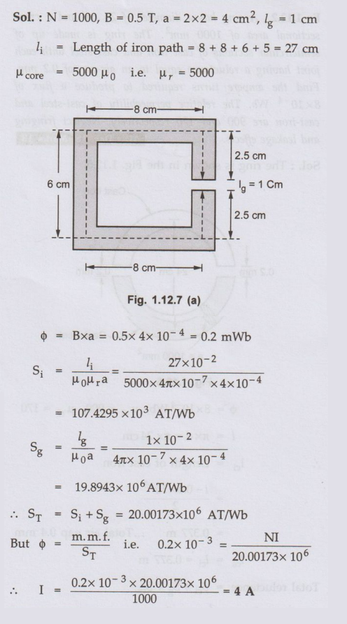
1.12.4 For the magnetic circuit shown in Fig. 1.12.7
determine the current required to establish a flux density of 0.5 T in the air
gap. AU : Dec.-10, Marks 12
Sol. :
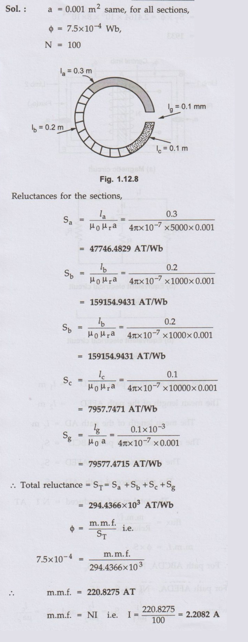
Ex.
1.12.5 A ring composed of three sections. The cross
section area is 0.001 m2 for each section. The mean arc length are la
= 0.3 m, lb = 0.2 m, lc = 0.1 m, an air gap length of 0.1
mm is cut in the ring, µr for sections a, b and c are 5000, 1000 and
10000 respectively. Flux in the air gap is 7.5x10⁻⁴ Wb. Find i)
m.m.f. ii) Exciting current if the coil has 100 turns iii) Reluctance of the
sections. AU : Dec.-11, Marks 16
Sol. :
Ex.
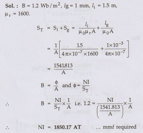
1.12.6 A flux density of 1.2 Wb/m2 is required in 1 mm
air gap of an electromagnet having an iron path of 1.5 m long. Calculate the
mmf required. Given the relative permeability of iron = 1600. AU : Dec.-19,
May-13, Marks 8
Sol.
:
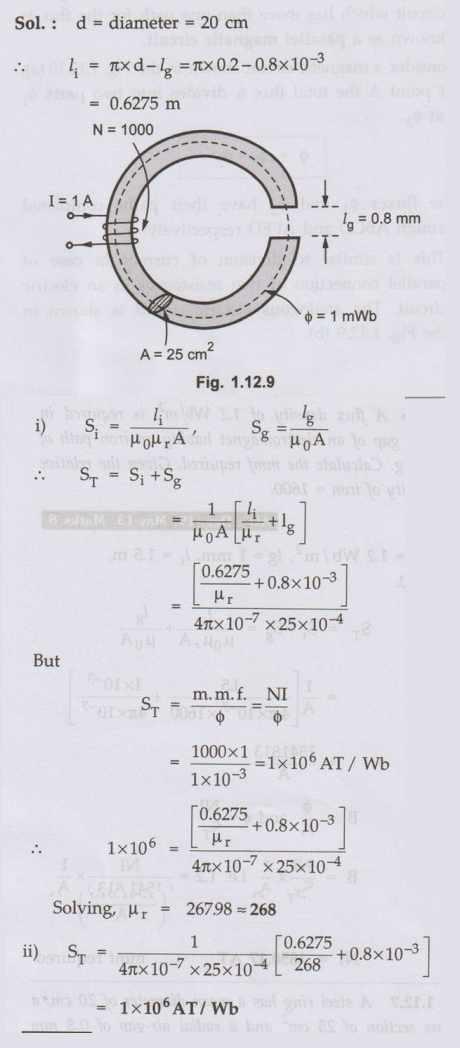
Ex 1.12.7
A steel ring has a mean diameter of 20 cm, a cross section of 25 cm2
and a radial air-gap of 0.8 mm cut across it. When excited by a current of 1 A
through a coil of turns 1000 wound on the ring core, it produces an air-gap
flux of 1 mWb. Neglecting leakage and fringing. Calculate i) Relative permeability of steel and ii)
Total reluctance of the magnetic circuit AU : Dec.-13, Marks 16
Sol. :
3. Parallel Magnetic Circuit
•
In case of electric circuits, resistances can be connected in parallel. Current
through each of such resistances is different while voltage across all of them
is same. Similarly different reluctances may be in parallel in case of magnetic
circuits. A magnetic circuit which has more than one path for the flux is known
as a parallel magnetic circuit.
Consider
a magnetic circuit shown in the Fig. 1.12.10 (a).

At
point A the total flux ϕ divides into two parts ϕ1 and ϕ2
ϕ
= ϕ1 + ϕ2
The
fluxes ϕ1 and ϕ2 have their paths completed through ABCD
and AFED respectively.
This is similar to division of current in case of parallel connection of two resistances in an electric circuit. The analogous electric circuit is shown in the Fig. 1.12.9 (b).
The mean length of path
ABCD = l1 m
The mean length of path
AFED = l2 m
The mean length of path AD
= lc m
The reluctance of path
ABCD = S1
The reluctance of path
AFED = S2
The reluctance of path AD
= SC
The total m.m.f. produced
= N I AT
flux = m.m.f. /
Reluctance
m.m.f. = ϕ × S
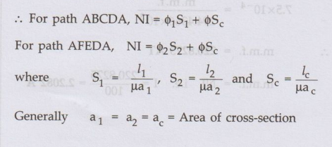
For
parallel circuit,
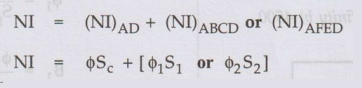
Total
m.m.f. required by central limb + m.m.f. required by any one outer limbs
As
in the electric circuit e.m.f. across parallel branches is same, in the
magnectic circuit the m.m.f. across parallel branches is same.
Thus
same m.m.f. produces different fluxes in the two parallel brancges. For such
parallel branches,
ϕ1 S1 = ϕ2 S2
Hence
while calculating total m.m.f., the m.m.f. of only one of the two parallel
branches must be considered
4. Parallel Magnetic Circuit with Air Gap
Consider
a parallel magnetic circuit with air gap in the central limb as shown in the
Fig. 1.12.11.
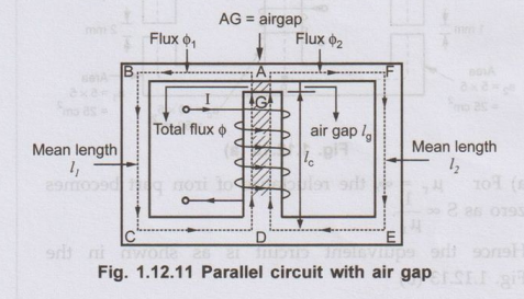
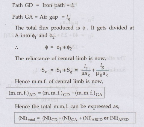
The analysis of this circuit is exactly
similar to the parallel circuit discussed above. The only change is the
analysis of central limb. The central limb is series combination of iron path
and air gap. The central limb is made up of,
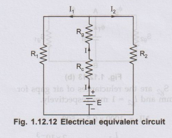
Thus
the electrical equivalent circuit for such case becomes as shown in the Fig.
1.12.12.
Similarly
there may be air gaps in the side limbs but the method of analysis remains the
same.
Ex. 1.12.8 For
the magnetic circuit shown in Fig. 1.12.13, with a core thickness 5 cm,
exciting current of 0.5 A with 1000 turns coil, find the flux density and flux
in each of the outer limbs and the central limbs. Assume relative permeability
for iron of the core to be a) infinity b) 4500.
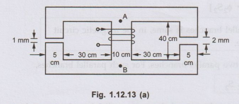
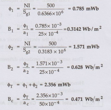
Sol. : The fluxes are shown
in the Fig. 1.12.13 (a)
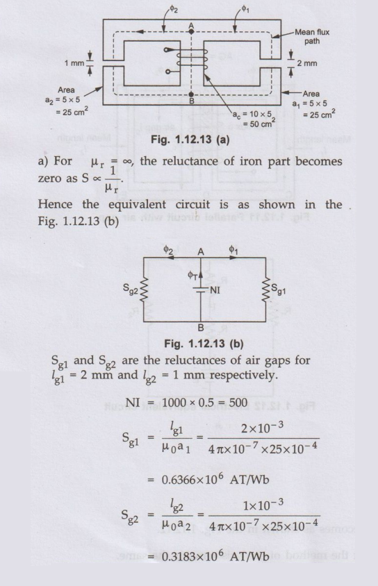
Key Point :
The m.m.f. (NI) remains same for the parallel paths.
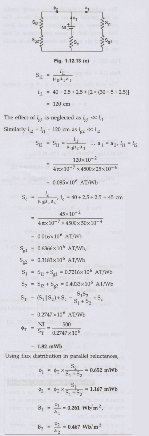
b)
For µr = 4500, the equivalent circuit is as shown in the Fig.
1.12.13 (c)
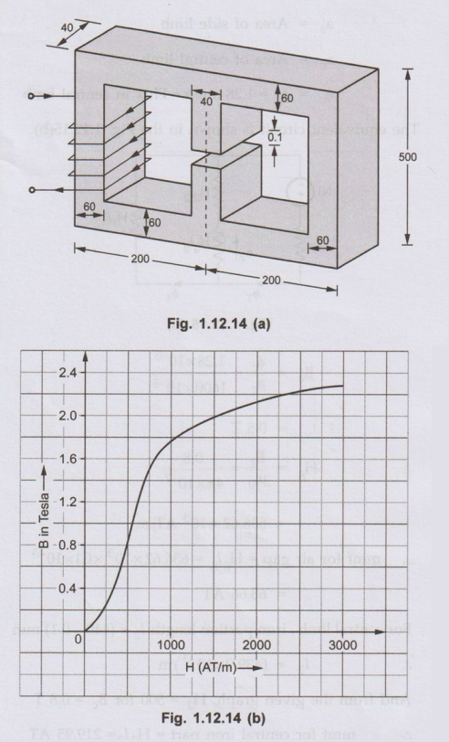
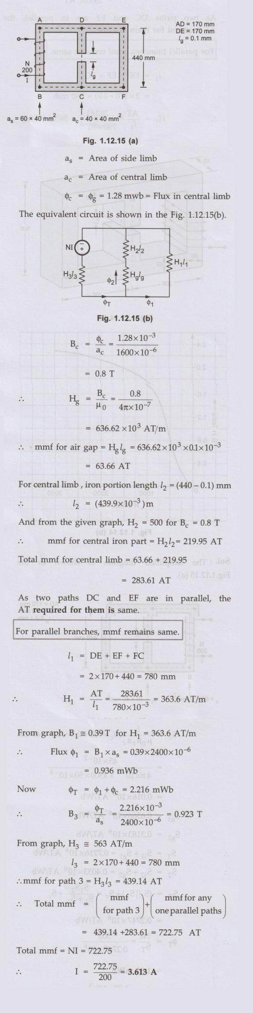
Ex. 1.12.9
In the magnetic circuit detailed in Fig. 1.12.14 (a) with all dimensions in
mm, calculate the required current to be passed in the coil having 200 turns in
order to establish a flux of 1.28 mWb in the air gap. Neglect fringing effect
and leakage flux. The B-H curve of the material is given in Fig. 1.12.14 (b).
Permeability of air may be taken as µ0 = 41x10-2 H/m. AU
: May-19, Marks 15
Sol.
:
The
simplified diagram is shown in the Fig.1.12.15 (a).
Review Questions
1. Discuss in detail
about magnetic circuits. AU : May-11, Marks 5
2. Draw and explain
the typical magnetic circuit with air-gap and its equivalent electric circuit.
Hence derive the expression for air-gap flux. AU : Dec.-17, May-13, 14, Marks
16
3. A steel ring of 180 cm mean diameter has a cross sectional area of 250 mm2. Flux developed in the ring is 500 u Wb when a 4000 turns coil carries certain current. Find i) m.m.f. required ii) reluctance iii) current in the coil. Given that the relative permeability of the steel is 1100.
(Ans. : 8181.72 AT, 1.6363 x 10⁷, 2.045 A)
4. A coil is wound
uniformly with 300 turns over a steel ring of relative permeability 900, having
mean circumference of 40 mm and cross-sectional area of 50 mm2. If a
current of 25 A is passed through the coil, determine
i) m.m.f. ii)
reluctance of ring and iii) flux.
(Ans. : 7500 AT, 707355.3 AT/Wb, 0.0106 Wb)
5. Find the number of
ampere turns required to produce a flux of 0.44 milli-weber in an iron ring of
100 cm mean circumference and 4 cm2 in cross-section. B Vs ur test
for the iron gives the following result :
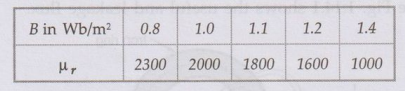
If a saw cut of 2 mm wide is made in the above ring, how many extra ampere turns are required to maintain same flux ?
(Ans. : 486.307 AT, 1744 AT)
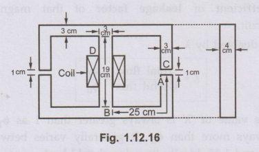
6. The Fig. 1.12.16
shows a magnetic circuit with two similar branches and an exciting coil of 1500
turns on central limb. The flux density in the air gap is 1 Wb/m2 and
leakage coefficient 1.2. Determine exciting current through the coil. Assume
relative permeability of the iron constant equal to 600.
(Ans. : I = 6.2388 A)
7. A magnetic circuit
has the mean length of flux path f 20 cm, and cross sectional area of 1 cm2.
Relative permeability of its material is 2400. Find the m.m.f. required to
produce a flux density of 2 tesla in it. If an airgap of 1 mm is introduced in
it, find the m.m.f. required for the air gap as a fraction of the total m.m.f.
to maintain the same flux density.
(Ans. : 0.9234 times total m.m.f)
Electrical Machines: Unit I: a. Magnetic Circuits and Electromagnetism : Tag: : - Magnetic Circuits
Related Topics
Related Subjects

Electrical Machines I
EE3303 EM 1 3rd Semester EEE Dept | 2021 Regulation | 3rd Semester EEE Dept 2021 Regulation