Electromagnetic Theory: Unit III: (b) Magnetic Forces, Magnetic Materials and Inductance
Magnetic circuits
with Example Solved Problems
• In general, in magnetic circuits, we determine the magnetic fluxes and magnetic field intensities in various parts of the circuits.The magnetic circuits are analogous to the electric circuits.
Magnetic circuits
AU
: May-04, 10, 13, 16, 18, Dec.-14
•
In general, in magnetic circuits, we determine the magnetic fluxes and magnetic
field intensities in various parts of the circuits. The magnetic circuits are
analogous to the electric circuits. If we study this analogy between the
electric and magnetic circuits, we can achieve simple techniques for analysis
of the magnetic circuits. Also we can directly use the concepts of the electric
circuits in solving the magnetic circuit problems.
•
The common examples of the magnetic circuits are transformers, toroids motors,
generators, relays and magnetic recording devices.
•
Let us study analogy between the electric and magnetic circuits. An electric
circuit forms a circuit (i.e. closed path) through which current can flow.
Similar to this magnetic lines of flux are continuous and can form closed
paths. So a single magnetic line of flux
or all parallel magnetic lines of flux may be considered as magnetic circuit.
•
Similar to electromotive force (e.m.f.) in an electric circuit, we can define a
new quantity in case of a magnetic circuit called magnetomotive force (m.m.f.).
The magnetomotive force (m.m.f.) is defined as,

•
The SI unit of m.m.f. is ampere (A). But generally, in magnetic circuits, the
source of m.m.f. is a coil carrying conductors with N number of turns as shown
in the Fig. 8.9.1 (c). Thus m.m.f. is measured in ampere-turn (A-t) very often.
Note that m.m.f. is not a force measured in newton.
•
In an electric circuit, resistance is defined as the ratio of voltage to
current given by
R
= V / I
•
In case of analogous magnetic circuits, we define a new quantity reluctance (R)
as the ratio of the magnetomotive force to the total flux.
Ɽ
= em / ϕ ….. (8.9.2)
The
reluctance is measured in Ampere . turn / Weber
•
The resistance in electric circuit can be expressed interms of conductivity σ
as
R
= l / σS
where
l
= Length in m
S
= Cross-sectional area in m2
σ
= Conductivity of the linear isotropic homogeneous material.
•
In case of magnetic circuits, we can define reluctance in very much similar way
as,
R
= l / µS ... (8.9.3)
where µ = Permeability of the isotropic, linear
homogeneous material
•
For electric circuit, Ohm's law can be expressed in point from as,

•
Now consider magnetic circuit. The magnetic flux density is analogous to the
current density, thus we can write,
•
The basic equations derived in magnetostatics are very much helpful in the
analysis of the magnetic circuits. These basic equations are

•
In other form, the two equations can be expressed in terms of the total current
flowing in the magnetic circuit and the total magnetic flux density through
cross-section of the magnetic circuit.
•
The total current in the magnetic circuit is given by,

•
The total magnetic flux density flowing through the cross-section of the
magnetic circuit is given by

•
In electric circuit, The reciprocal of the resistance is called conductance. In
magnetic circuits, the reciprocal of the reluctance is called permeance denoted
by p The permeance is measured in henries (H).
P
= µS / l ... (8.9.9)
•
The analogous electric and magnetic circuits can be represented in simple way
as shown in the Fig. 8.9.1.

•
In electric circuits we can apply basic Kirchhoff s laws; such as Kirchhoff's
Current Law (KCL) at the node and Kirchhoff's Voltage Law (KVL). We can apply
the same laws to the magnetic circuits. There are two laws namely Kirchhoff's
flux law and Kirchhoff’s m.m.f. law.
•
Kirchhoff's flux law states that the total magnetic flux
arriving at any junction in a magnetic circuit is equal to the total magnetic
flux leaving that junction. Using this law, parallel magnetic circuits can be
easily analyzed. Mathematically, Kirchhoff's flux law at a junction can be
expressed as,
∑
ϕ = 0
... (8.9.10)
•
Kirchhoff's m.m.f. law states that the resultant m.m.f.
around a closed magnetic circuit is equal to the algebraic sum of products of
flux and reluctance of each part of the closed circuit. For closed magnetic
circuit,
∑
M. M. F = ∑ ϕ R ... (8.9.11)
•
Kirchhoff's m.m.f. law can be alternatively stated as
resultant m.m.f. around any closed loop of a magnetic circuit is equal to the
algebraic sum of the products of the magnetic field strength and the length of
each part of the circuit. Hence we can write,
∑
M. M. F = ∑ H . l ... (8.9.12)
•
Inspite of having analogous behaviour of the magnetic circuits with the
electric circuits, it is very difficult to carryout exact analysis of the
magnetic circuits. The difficulties in the analysis are due to the following
points.
•
In general, the magnetic circuits are made up of ferromagnetic material. The
permeability of ferromagnetic materials depends on the magnentic field
intensity ![]() .
.
•
Secondly, it is difficult to control and calculate the leakage flux which
strays or leaks from the main path of the flux in the magnetic circuit.
• Lastly if there is an air gap in between the path of the magnetic flux, it spreads and bulges out. This effect is called fringing effect.
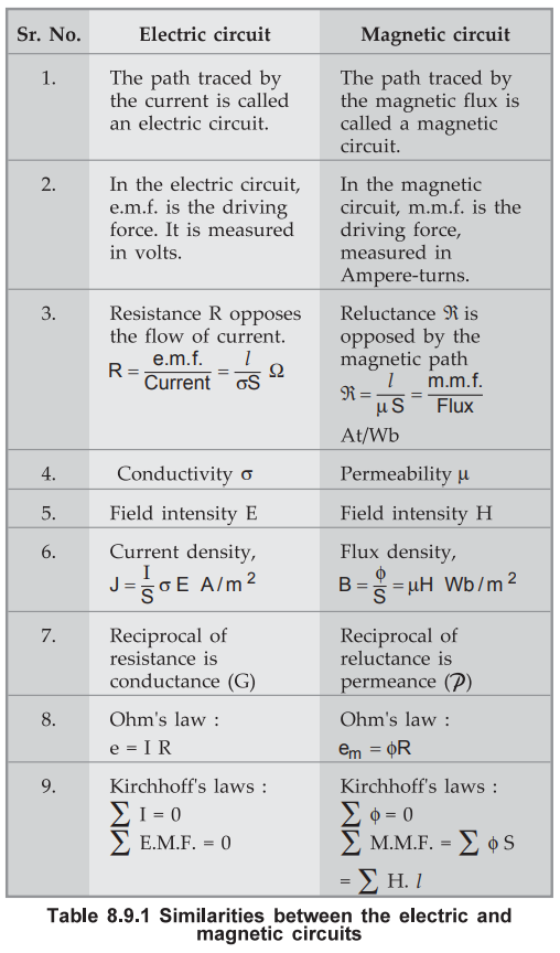
The
analogy between the electric circuit and magnectic circuit is summarized in
Table 8.9.1.
•
The dissimilarities between the electric and Magnetic circuit are given in
Table 8.9.2.

Ex.
8.9.1 An iron ring with a cross-sectional area of 3 cm2 and a mean
circumference of 15 cm is wound with 250 turns wire carrying a current of 0.3
A. The relative permeability of the ring is 1500. Calculate the flux
established in the ring.
AU:
Dec.-14, Marks 8, May-18, Marks 13
Sol.
: The
magnetic field intensity is given by,
H
= I / 2лг = I/C = 0.3 / 15 × 10-2 = 2 A/m
where
C = Circumference
But
B = µH = µ0 µr H
=
4 × π × 10-7 × 1500 × 2 = 3.7699 × 10⁻³ T
The
flux induced in one turn of a iron ring is given by,
ϕ
= B.S where
S
= Area of cross-section of iron ring
=
(3.7699 × 10⁻³) (3 × 10⁻⁴)
=
1.13097 × 10⁻⁶ Wb
Hence
the total flux established in the ring for N number of turns is given by,
ϕTotal
= N. ϕ = 250. (1.13097 × 10⁻⁶)
=
0.2827 mWb
Ex. 8.9.2 An iron ring with a cross-sectional area of 3 cm2 and a mean circumference of 15 cm is wound with 250 turns of wire carrying a current of 0.3 A. The relative permeability of the ring is 1500.
i)
Calculate the flux established in the ring.
ii)
If a saw cut of width 2 mm is made in the above ring, find the new value of the
flux in the circuit.
Sol.
:
For solution of i), refer example 8.9.1.
ii)
With saw cut air gap in a iron ring, total reluctance is given by,
RT
= Reluctance of iron ring + Reluctance of air gap

Ex.
8.9.3 An iron ring with a cross sectional area of 8 cm and a mean circumference
of 120 cm is wound with 480 turns of wire carrying a current of 2 A. The
relative permeability of the ring is 1250. Calculate the flux established in
the ring.

The
magnetic field intensity is given by,

The
flux induced in one turn of an ion ring is given by,

Hence
the total flux induced in the iron ring of 480 turns is given by,

Ex.
8.9.4 A coil has 1000 turns and carries a magnetic flux of 10 mWb. The
resistance of the coil is 4 Q. If it is connected to a 40 V d.c. supply,
estimate the energy stored in the magnetic field when the current attains its
final steady state value.
Sol.
:
Given : N = 1000, ϕ = 10 mWb = 10 × 10-3 Wb,
R
= 4 Ω,
V = 40 V
The
current in the coil at steady state is given by,
I
= V / R = 40 / 4 = 10 A
Hence
the self inductance of a coil is given by,
L
= N ϕ
/ I = 1000 × 10 × 10-3 / 10 = 1 H
Thus
the energy stored in a magnetic field is given by,
Wm
= 1/2 LI2 = 1/2 (1) (10)2 = 50 W
Examples
for Practice
Ex.
8.9.5 A cast iron C core has a mean length of 0.44 m with
square cross-section 0.02 × 0.02 m. The air gap length is 2 mm and the coil has
400 turns. Find the current required to establish an air gap of 0.141 mWb, µr =
328.
[Ans.
: 2.0932 A]
Ex.
8.9.6 A magnetic circuit employes an air core toroid with
500 turns, cross sectional area 6 cm2, mean radius 15 cm and 4 A
coil current. Determine reluctance of the circuit, flux density and magnetic
field intensity.
[Ans.
: 1.25 × 10⁹ A. t / Wb, 1.6 × 10⁻⁶ Wb 2.667 × 10⁻³
T, 2122.1 A.t/m]
Review Questions
1. Explain the relation between field theory and circuit theory.
2. Tabulate the similarities and dissimilarities of the electric
and magnetic circuits.
3. Define a magnetic circuit with a sketch and hence obtain the
expression for its reluctance.
Electromagnetic Theory: Unit III: (b) Magnetic Forces, Magnetic Materials and Inductance : Tag: : with Example Solved Problems - Magnetic circuits
Related Topics
Related Subjects

Electromagnetic Theory
EE3301 3rd Semester EEE Dept | 2021 Regulation | 3rd Semester EEE Dept 2021 Regulation