Electrical Machines: Unit I: a. Magnetic Circuits and Electromagnetism
Magnetic Field due to Straight Conductor
When a straight conductor carries a current, it produces a magnetic field all along its length. The lines of force are in the form of concentric circles in the planes right angles to the conductor. This can be demonstrated by a small experiment.
Magnetic
Field due to Straight Conductor
• When a straight conductor carries a current,
it produces a magnetic field all along its length. The lines of force are in
the form of concentric circles in the planes right angles to the conductor.
This can be demonstrated by a small experiment.
•
Consider a straight conductor carrying a current, passing through a sheet of
cardboard as shown in the Fig. 1.7.1. Sprinkle iron fillings on the cardboard.
Small tapping on the cardboard causes the iron filling to set themselves, in
the concentric circular pattern. The direction of the magnetic flux can be
determined by placing compass needle near the conductor. This direction depends
on the direction of the current passing through the conductor. For the current
direction shown in the Fig. 1.7.1 i.e. from top to bottom the direction of flux
is clockwise around the conductor.

•
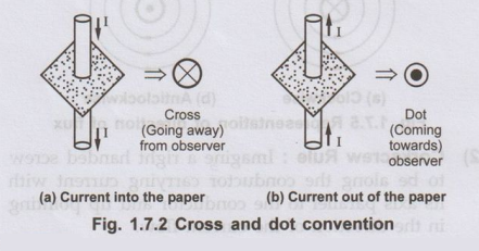
Conventionally such current carrying conductor is represented by small circle,
(top view of conductor shown in the Fig. 1.7.1). Then current through such
conductor will either come out of paper or will go into the plane of the paper.
Key Point :
When current is going into the plane of the paper, i.e. away from observer, it
is represented by a 'cross', inside the circle indicating the conductors.
The
cross indicates rear view of feathered end of an arrow.
Key Point :
The current flowing towards the observer i.e. coming out of the plane of the
paper is represented by a 'doť inside the circle.
The dot indicates front view i.e. tip of an arrow. This is shown in the Fig. 1.7.2
1. Rules to Determine Direction of Flux Around Conductor
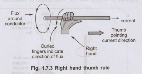
1) Right Hand Thumb Rule :
It states that, hold the current carrying conductor in the right hand such that
the thumb pointing in the direction of current and parallel to the conductor,
then curled fingers point in the direction of the magnetic field or flux around
it. The Fig. 1.7.3 explains the rule.
Let
us apply this rule to the conductor passing through card sheet considered
earlier. This can be explained by the Fig. 1.7.4.
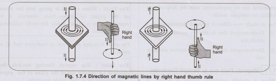
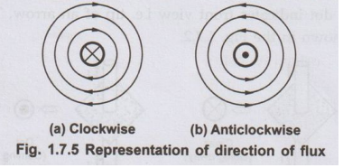
Conventionally it is shown in the Fig.1.7.5
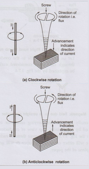
2) Corkscrew Rule :
Imagine a right handed screw to be along the conductor carrying current with
its axis parallel to the conductor and tip pointing in the direction of the
current flow.
Then
the direction of the magnetic field is given by the direction in which the
screw must be turned so as to advance in the direction of the current. This is
shown in the Fig. 1.7.6.
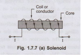
2. Magnetic Field due to Circular Conductor i.e. Solenoid
A
solenoid is an arrangement in which long conductor is wound with number of
turns close together to form a coil. The axial length of conductor is much more
than the diameter of turns. The part or element around which the conductor is
wound is called as core of the solenoid. Core may be air or may be some
magnetic material. Solenoid with a steel or iron core in shown in Fig. 1.7.7
(a).
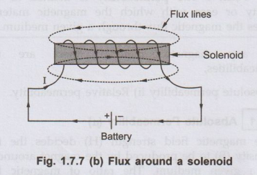
When
such conductor is excited by the supply so that it carries a current then it
produces a magnetic field which acts through the coil along its axis and also
around the solenoid. Instead of using a straight core to wound the conductor, a
circular core also can be used to wound the conductor. In such case the
resulting solenoid is called Toroid. Use of magnetic material for the core
produces strong magnet. This is because current carrying conductor produces its
own flux. In addition to this, the core behaves like a magnet due to magnetic
induction, producing its own flux. The direction of two fluxes is same due to
which resultant magnetic field becomes more strong.
The
pattern of the flux around the solenoid is shown in the Fig. 1.7.7 (b).
The rules to determine the
direction of flux and poles of the magnet formed :
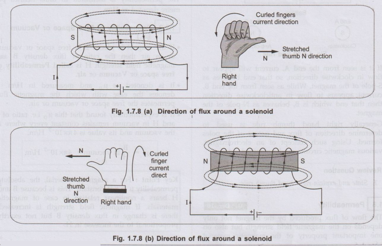
1) The right hand thumb rule :
Hold the solenoid in the right hand such that curled fingers point in the
direction of the current through the curled conductor, then the outstretched
thumb along the axis of the solenoid point to the North pole of the solenoid or
point the direction of flux lines inside the core.
This
is shown in Fig. 1.7.8 (a) and (b).
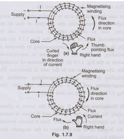
In
case of toroid, the core is circular and hence using right hand thumb rule, the
direction of flux in the core, due to current carrying conductor can be
determined. This is shown in the Fig. 1.7.9 (a) and (b). In the Fig. 1.7.9 (a),
corresponding to direction of winding, the flux set in the core is
anticlockwise while in the Fig. 1.7.9 (b) due to direction of winding, the
direction of flux set in the core is clockwise. The winding is also called
magnetising winding or magnetising coil as it magnetises the core. (See Fig.
1.7.9 (a), 1.7.9 (b)
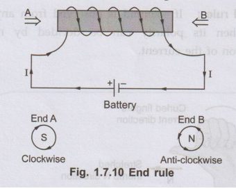
Consider
solenoid shown in the Fig. 1.7.10.
2) Corkscrew rule :
If axis of the screw is placed along the axis of the solenoid and if screw is
turned in the direction of the current, then it travels towards the N-pole or
in the direction of the magnetic field inside the solenoid.
3) End rule :
If solenoid is observed from any one end then its polarity can be decided by
noting direction of the current.
•
If it is seen from the end A, current will appear to flow in clockwise
direction, so that end behaves as S-pole of the magnet. While as seen from the
end B, current appears to flow in anticlockwise direction then that end which
is B, behaves as N-pole of the magnet.
•
Generally right hand thumb rule is used to determine direction of flux and
nature of the poles formed. Using such concept of an electromagnet, various
magnetic circuits can be obtained.
Review Question
1. State and explain
right hand thumb rule.
Electrical Machines: Unit I: a. Magnetic Circuits and Electromagnetism : Tag: : - Magnetic Field due to Straight Conductor
Related Topics
Related Subjects

Electrical Machines I
EE3303 EM 1 3rd Semester EEE Dept | 2021 Regulation | 3rd Semester EEE Dept 2021 Regulation